The Old Z Axis Endstop
I'm kind of old-school in my printer designs. I like things to be as close mechanically perfect as I can figure out how to make them, instead of putting sensors everywhere and hoping the controller's firmware can compensate for poor materials or construction. If you've followed any of my blog posts on UMMD you'll know I prefer to use a flat print bed, accurately trammed instead of putting a bed sensor on the extruder carriage. I also prefer to use endstop switches in all axes.
When I built UMMD one of the things I put some extra effort into was a finely adjustable Z=0 endstop. I used a lever and cam to effectively reduce the adjusting screw movement to approximately 100 um per rev of the screw. It has worked well and reliably for a few years but during recent work on the machine I noticed some things I didn't like, leading me to redesign the whole thing.

The main problem is that the switch is mounted solidly on the frame of the printer and the adjuster/lever/cam are mounted solidly on the moving part of the Z axis. Over the last few years as I've swapped out hot-ends and extruders, changed a few things in the Z axis, and rezeroed the bed a number of times, the adjuster has crashed into the switch a few times. The result is that the switch has put some dents in the cam so adjustment isn't as smooth and reliable as it was when the whole thing was new.
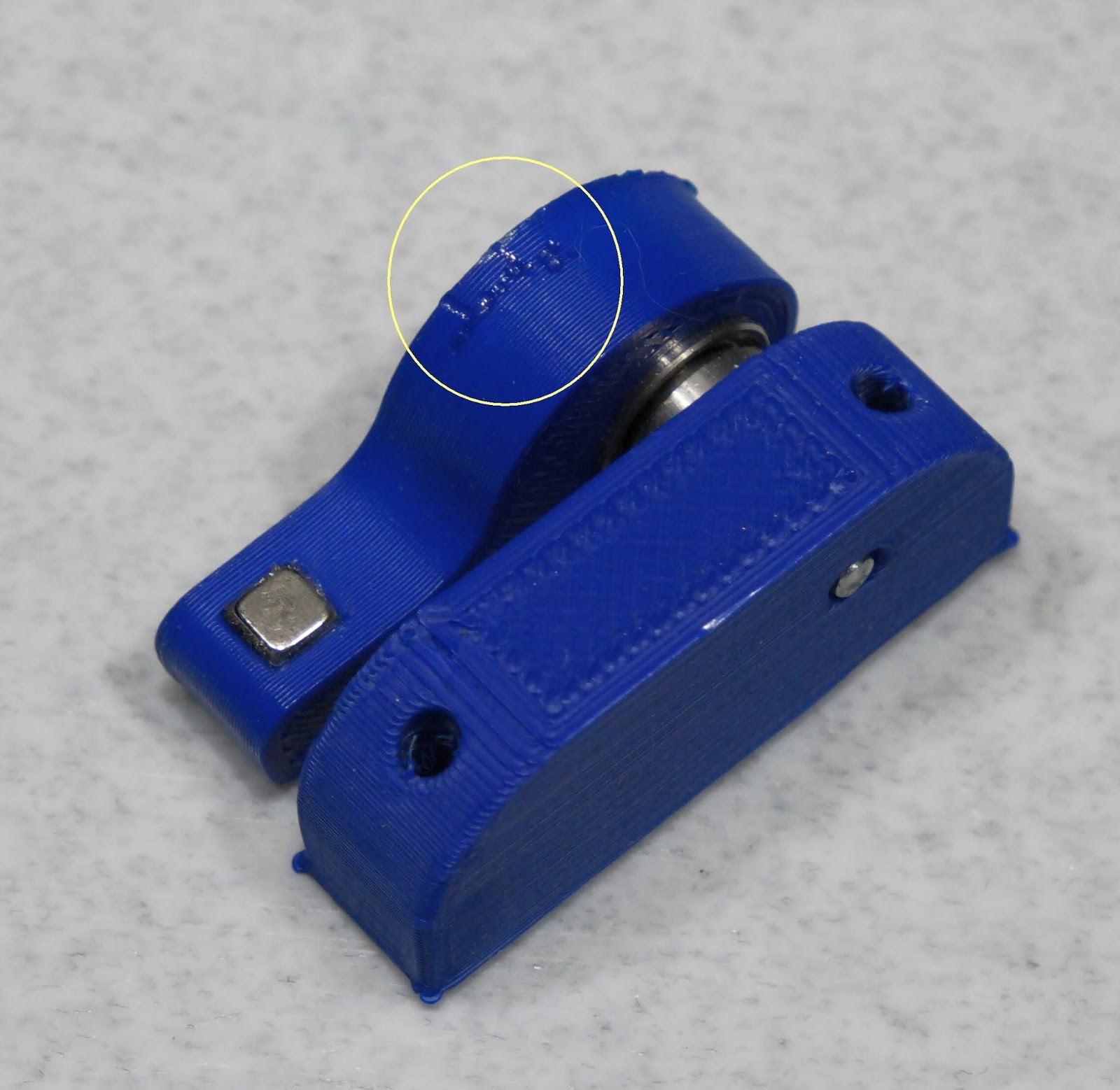 |
| This is the lever/cam assembly that used to bump the microswitch. It has become a problem to set the Z=0 position because the dents in the cam no longer trigger the switch the way the smooth surface used to. |
I could print a new lever and cam but that wouldn't prevent the problem from happening again, and making it out of metal seems like a lot of trouble. The way the switch is mounted is a big part of the problem. It should not be set in opposition to the motion of the Z axis. After changing to optical endstops in the X and Y axes, I decided to do the same in Z with the intention of mounting the endstop so that if the bed moves up beyond the endstop it won't damage anything.
I could just mount the switch on a spring that would allow it to move a bit if the cam bangs into it too hard, but there are other considerations as well. The original lever and cam design worked pretty well, but it wasn't really linear so I could never be sure of the exact amount of movement I was getting when I turned the adjuster screw. I wanted to get 100 um per rev of the adjuster screw so that I could accurately move the bed in small amounts like 20-50 um. I decided to look for an alternative and discovered something called a "differential screw".
How It Works
There are different ways to implement a differential screw. The one I chose has two different thread pitches along its length. One end of the screw turns in a fixed nut, the other is in a sliding nut. If you turn the screw clockwise, it moves into/through the fixed nut and into/through the sliding nut. The net movement of the sliding nut is the difference between the two pitches. The sliding nut movement is in the direction of the screw movement if the larger pitch screw is the one threaded through the fixed nut.
This video illustrates the concept:
A more compact approach is to have a screw inside a threaded tube that has one pitch on the inside and a different pitch on the outside. Like this:
If you have deep pockets you can buy off-the-shelf differential screws from specialty mechanical parts companies. Beware the ~$20 "differential screw micrometers" being sold on ebay. They appear to be simple 0.5 mm pitch screws with a nice knob. I don't have the deep pockets for a real differential screw, and since I wanted 0.1 mm per turn of the screw, I looked for standard screws that had 0.1 mm difference in their pitches. A look at a metric thread pitch table reveals multiple possibilities.
| Size - Nominal Diameter (mm) | Pitch1) (mm) | Clearance Drill (mm) | Tap Drill (mm) | Tensile Stress Area (mm) |
|---|---|---|---|---|
| M 1.6 | 0.35 | 1.8 | 1.25 | |
| M 2 | 0.40 | 2.4 | 1.60 | |
| M 2.5 | 0.45 | 2.90 | 2.00 | |
| M 3 | 0.50 | 3.40 | 2.50 | |
| M 3.5 | 0.60 | 3.90 | 2.90 | |
| M 4 | 0.70 | 4.50 | 3.30 | 8.78 |
| M 5 | 0.80 | 5.50 | 4.20 | 14.2 |
| M 6 | 1.00 | 6.60 | 5.00 | 20.1 |
| M 8 | 1.25 | 9.00 | 6.80 | 36.6 |
| M 10 | 1.50 | 12.00 | 8.50 | 58.0 |
| M 12 | 1.75 | 14.00 | 10.20 | 84.3 |
| M 14 | 2.00 | 16.00 | 12.00 | |
| M 16 | 2.00 | 18.00 | 14.00 | 157 |
| M 20 | 2.50 | 22.00 | 17.50 | 245 |
| M 22 | 2.50 | 25.00 | 19.50 | |
| M 24 | 3.00 | 27.00 | 21.00 | 353 |
| M 27 | 3.00 | 30.00 | 24.00 | |
| M 30 | 3.50 | 33.00 | 26.50 | 561 |
| M 36 | 4.00 | 40.00 | 32.00 | 817 |
| M 42 | 4.50 | 46.00 | 37.50 | 1120 |
| M 48 | 5.00 | 53.00 | 43.00 | 1470 |
| M 56 | 5.50 | 62.00 | 50.50 | 2030 |
| M 64 | 6.00 | 70.00 | 58.00 | 2680 |
| M 68 | 6.00 | 74.00 | 62.00 |
1) For metric threads pitch is the distance between threads.
This table comes from: https://www.engineeringtoolbox.com/metric-threads-d_777.html
There are multiple pairs of screws that could be used to get 100 um per turn sensitivity (M3/M3.5, M3.5/M4, M4/M5), and even some that could give 50 um per turn (M1.6/M2, M2/M2.5, M2.5/M3), but those screw sizes are relatively uncommon, especially in the long lengths (70 mm or so for my application) needed.
I selected the M5/M4 combo. Every turn of the M5 screw moves the screw forward 0.8 mm and moves the sliding M4 nut back 0.7 mm leaving a net forward motion of 0.1 mm at the sliding nut. If I use the sliding nut to activate my endstop switch, I'll have a very finely adjustable endstop, and unlike my previous lever/cam arrangement, every turn of the screw should give exactly 100 um with accuracy limited by the screw thread quality. This technique can be used to bump a mechanical switch or to trigger an opto interruptor.
One problem with this arrangement is limited range of motion at the output. If I turn the M5 screw 10 times, the screw will move 8 mm. The sliding nut will move 1 mm in the same direction as the screw. So if I want 10mm adjustable output range, the 5mm screw would have to be at least 80mm long and the 4mm screw at least 70mm long. Not even UMMD has room for a 150mm long Z=0 screw. Nope, I won't be adjusting the screw over a 10 mm range.
UMMD's opto endstop mounts on the Z axis vertical T-slot frame so the endstop can easily be repositioned within the adjustment range of the differential screw, so I settled on a reasonable differential screw adjustment range of 2 mm. The 5mm screw has to move 16mm and the 4mm screw 14mm. That means the exposed thread length of the screw has to be 30 mm plus the thicknesses of the fixed nut, the thumbwheel, the sliding nut and the mount.
Making a Differential Screw
Someone at the makerspace suggested that I could drill holes in the ends of the screws and use a pin to hold them together, but I couldn't figure out a good way to accurately drill a ~1 mm hole in the axial center of a screw.
Another suggestion was to make a coupling nut that was threaded for M5 on one side and M4 on the other and then just screw it together with locktite or epoxy to ensure it can't easily come apart. This is probably the easiest way to go, but adds the length of the coupling nut to the screw.
Finally, someone else at the makerspace suggested that I drill and tap a block of metal, then split it with a saw and use it as a clamp to hold the screws for welding.
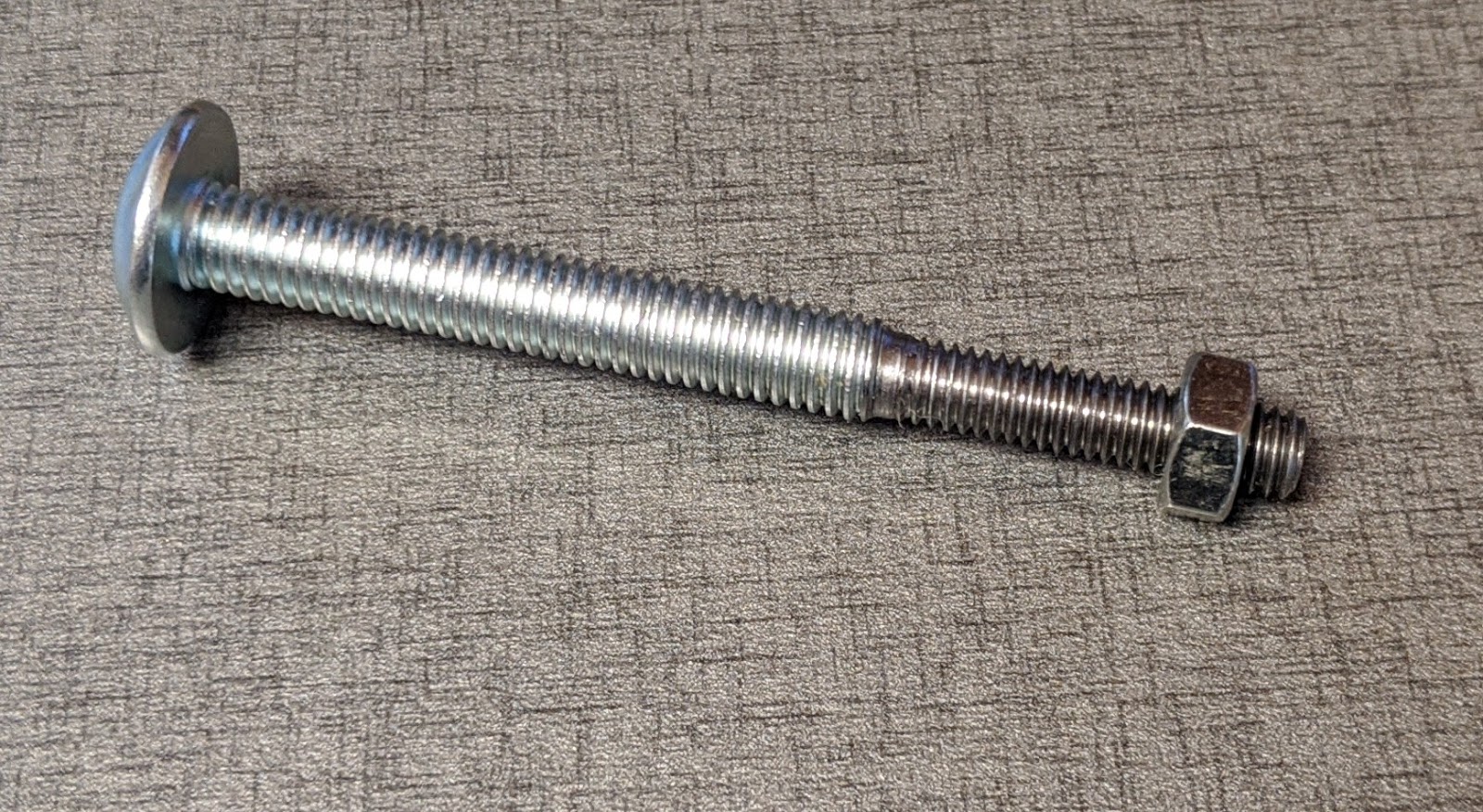
In the end, I mounted a 50mm long M5 screw in a collet on a lathe and turned the end 20 mm down to 4 mm diameter, then threaded it with an M4 die. It was actually pretty quick and easy, mostly because I had help from an expert lathe operator at the makerspace.
 |
| Turning the M5 screw on the lathe. M5x0.8mm threads have a minor diameter that is about 4 mm, so essentially, all you have to do is turn it down until the threads disappear. I made four or five passes making very shallow cuts so that the cutter wouldn't deflect the screw too much as it was cutting it. After the screw was turned down to about 4 mm diameter, I rotated the cutter and beveled the end of the screw. |
 |
| Once the M5 threads were removed and the end of the screw was beveled, I used a die to manually cut the M4x0.7 mm threads into the end of the screw. The end of the tailstock on the lathe (not visible in the picture) was used to ensure that the die was started square to the screw. |
 |
| Testing the M4 threads after cutting them. Yup, it works! |
 |
| The almost finished differential screw. I still have to grind flats on the head so I can turn the screw with a printed thumbwheel. |
The Rest of the Parts
Once I had the screw, the rest was easy. I designed and printed a thumbwheel with 10 evenly spaced bumps to make it easy to set the position - just turn the screw by 1 bump for every 10 um of movement.
The base of the part (the red block under the bracket in the image below) is the fixed nut that the M5 screw threads into. I used a block of PTFE, 5mm thick, because it works well for that type of operation in the kinematic mount for the bed. I drilled an undersized hole and let the M5 screw roll its threads in the plastic. It is gripped firmly but still easily adjustable.
 | |
|
You can't tell from the picture, above, but if the opto endstop should fail and the bed keeps moving up, the square tube tube will have room to pass by the opto interruptor, so nothing will get damaged. The bearing blocks on the Z axis will eventually hit the physical stops.
The Fusion360 CAD file is here and the STL files of the printable parts are here.
 |
| Here are the pieces of the new Z=0 adjuster. The PTFE fixed nut (white) mounts on the belt clamp bracket as does the square tube (blue). The differential screw goes through the fixed nut and the bracket. The spring goes inside the square tube to keep the flag and M4 nut pushed against the screw threads. |
The opto endstop is screwed to a printed bracket that is held on the printer's Z axis vertical frame with a bolt and t-nut.
Assembly
 |
| This is what it looks like when it's assembled. |
 |
| And this is what it looks like when it is installed. |
Other Uses for Differential Screws
A few people on the 3D printing forums have suggested that a differential screw would be a good thing to use in a kinematic printbed mount since the adjustments in those are usually very small.People make focus-stacking rigs for macro photography using linear guides and stepper motors to move the camera or object being photographed in small steps as they capture a series of images that are later processed using stacking software to greatly increase the depth of focus in the final image. The typical way to do it relies on the relatively inaccurate microstepping to reposition the camera or object 10-50 um between images. It would be pretty easy to couple a differential screw to a sliding carriage. With a differential screw made using M5x0.8 mm and M4x0.7 mm threads, a full turn of the motor (200 steps, typically) will move the camera or object 100 um, so each full step of the motor will move the camera or object 0.5 um. That means you can use the relatively accurate full steps of the motor for fine positioning instead of relying on "iffy" microstepping.
If you wanted to make a laser engraver to make very small markings, or even a 3D printer to make very small parts, differential screws could be used to position the laser/extruder.
How about a motor driven microscope stage?
UPDATE 3/30/20
I have run some tests on the precision of the opto endstop and tested the differential screw adjuster. New post here.
This is wonderful!
ReplyDeleteThe lathe would also have been the way to accurately center-drill for 1mm pins to connect two screws, but that would only have aligned the two screws, not held them together. Your eventual solution looks much better to me!
If anyone wants to do this but needs more total travel, start with M5 threaded rod instead of a screw, and use two locknuts at the M5 end to hold the knob. (They make low-profile M5 locknuts that would be convenient here.) You'll want to use a live center and/or follower if you have substantially more stick-out, or you can do it in stages, with the threaded rod inside the lathe spindle, and just do a few centimeters at a time.
"Low Profile Nylon Lock Nut" is the search term for the nuts I found; be aware that they are commonly available in both RH and LH thread due to using them to attach potentially counter-rotating propellers in RC aviation.
In my case the screw proved long enough, but for something like a focus stacking rig, simply coupling two threaded rods together, say M6 and M5, using a modified coupling nut, would allow much longer travel. I'd drill out one half of an M5 coupling nut then thread it with an M6x1.0 tap. M6 and M5 screws plus a 200 step per rev motor would give 1 um per step.
DeleteHi Mark
ReplyDeleteRetired electronics engineer here in Canada trapped in the house due to virus situation around us... Can't express how happy I am I came across your blog - it's jammed to the ceiling with fantastic reading and concepts to learn. I'm currently building a "bed flinger" as you refer to them as my first printer, but it won't be my last. The valuable knowledge you are sharing on here is simply fantastic. I'll be busy for days trying to absorb it all. Thanks very much for your efforts to document everything you are doing !
Wow! Thanks! I'm glad you're finding some useful information here.
DeleteIf you need more movement range you could have two adjustment modes, course and fine. Instead of having the fixed block have threads, it would be smooth bore. Then a slot in the fixed block would holed a thumb wheel with an internal 5mm thread. The remainder of the setup is the same. Use the thumb wheel to move the 5mm threaded rod in or out without changing the 4mm slider. So one turn of the thumb wheel will move the 5mm threaded rod in or out 0.8mm. Once you get the setting as close as you can with the thumb wheel you then turn the knob on the 5mm threaded rod to get the final accurate position. It's a bit more complex but not too bad ... if you need the additional adjustable range of motion.
ReplyDeleteThat's how a lot of the commercial differential screws assemblies are made. It gives you a coarse range of maybe 10 mm with a couple mm of fine adjustment. In my application it isn't really needed, but there are certainly others where it could be useful.
DeleteIs there a reason you didn't make the flag also from PTFE and have the screw also roll its own threads in the flag, rather than using an anti-backlash spring? (It worked, just curious how you ended up making different choices.)
ReplyDeleteNot suggesting that you fix what ain't broke, but if someone *else* is thinking about this and thus is already thinking about using a lathe, and is starting from scratch, here's another idea.
If you let both sides roll their own threads, and use my idea above to hold the knob on with lock washers, you don't even need to cut off any threads from a bolt or even have two different diameters. You could just single-point two different pitches on the same diameter smooth rod. You could use any pitches available using the lathe's change gears, and you wouldn't have to worry about damaging the threads in the collet. Just single-point a fine section to a small relief, change the gears, and single-point a slightly coarser section. With 5mm rod, you could cut a M5x0.4 section and a M5x0.5 section. As long as the coarse thread is an available nut size you can use two nuts to hold a knob in place. Alternatively, not needing nuts at all, you could crush the threads and melt the crushed threads into a knob. In that case, you could put whatever pitch threads you like into whatever diameter rod you have; e.g. 3/8" x 0.5mm/0.4mm would work fine even though I doubt it fits any commercially-available nut. ☺
Anyway, not a suggestion that you should have done it differently, just another idea that might be useful to someone else doing something similar later.
Thanks for the ideas! It sounds like your machining skills are far beyond mine.
DeleteI recently saw that Harbor Freight Tools cheapo metric tap and die set includes M4x0.7 and M4x0.75 (French?) taps and dies. One could easily thread both pitches on a 4 mm rod and get 50 um per turn of the screw.
I didn't make the flag out of PTFE because it's pretty hard to machine it down to anything less that a few mm thick. Not sure, but it might be a little too translucent when you cut it thin enough to fit into the opto interruptor. If you were going to bump a switch with the 'flag" you could easily make it out of PTFE and let the screw roll its own threads.
3D printing was my gateway drug to hobby machining, so I owe my machine skills to hobby 3D printing pioneers like you! (I don't know exactly when you got started, but I've learned a lot from reading your blog and am profoundly grateful for you sharing your knowledge.) For what it's worth, single-pointing an external thread form isn't too hard if you have the right lathe tools.
DeletePolyoxymethylene (Delrin™ / POM / acetal / lots of other synonyms) machines very nicely and is available in black. Following your tip from when I cut PTFE bed mounts, I have let screws roll their own threads in POM, and it has worked great. It's cheaper than PTFE, particularly if you buy generic. You blogged about buying cheap PTFE on ebay, and I think I bought it from the same seller, and also bought black acetal from the same seller.
Be aware that the cheapest tap and die sets, like the one you mention, are heat treated carbon steel, not titanium-coated. That means they are just fine for most cases of chasing bad/damaged threads, but have some limitations for cutting new threads. You can usually chase damaged threads on harder classes of steel bolts because the damaged parts are usually already weakened by being damaged, though you still want to take it easy to avoid damaging the tap/die.
If you use them to cut mild steel, use plenty of cutting oil (like tap magic) and go slowly, clearing chips regularly. For cutting aluminum, cutting oil will help keep them from clogging. For cutting brass, they can and should be used dry.
My personal preference would be brass. I've found brass rod stock pretty cheap on ebay, though I can't find metric brass rod stock available on ebay stocked in the US. Sigh.
Again, just food for thought for the next person thinking about this, sharing because I've been thinking about this while considering following your lead in switching to optical limit switches for my printer. ☺
Thanks for the tips. I've been looking at brass rods for another project using a differential screw. I'll look for a better tap and die set.
DeleteThat tap and die set should be fine for brass. At least, for $18 it's totally what I would try first, and I would expect it to work well. It's just when it gets to cutting threads in steel that you want to be careful.
DeleteIt looks like McMaster has 4mm rod for about $9/meter and 5mm rod for about $14/meter https://www.mcmaster.com/metals/copper-brass-and-bronze/ultra-machinable-360-brass-rods-and-discs-8/
I tried cutting two different fine thread pitches in brass and discovered that my threading insert grabbed the brass and chattered. I went through several different approaches using up about 10" of ¼" brass rod before I decided that was a dead end, so I ordered a set of small metric dies like the HF one (not currently available at my local HF). I am now planning to do exactly the same thing you did, turning the end of an M5 screw down and cutting it to M4, once the dies arrive. I'm not printing a shield around the flag for now.
ReplyDeleteI'm printing all the plastic parts in PETG and cutting threads most of the way through; that leaves just enough uncut screw-rolled threads to act like a lock washer, and enough clean threads to not mangle the plastic. To do that, I use a spiral flute tap and cut until the point of the tap reaches the far end of the plastic, then back it out and test fit. If it's too tight, I run the tap back in with finger pressure (no tap handle) until it reaches the end of the cut section, then add the tap handle and give it one more turn. I do that until the test fit is good.
I just learned that M6x0.5 is a standard extra fine thread (used, for example, for kinematic adjustment on a laser optics set). A brass M6x0.5mm screw could relatively easily be center drilled and tapped M4x0.7 and used in a concentric differential screw with the M4x0.7 fixed to the moving stage, with an M6x0.5 hole in the reference stage, giving 0.2mm/turn of the outer M6x0.5 screw with the fixed M4x0.7 inside. That might be useful if someone needs a more compact design for a differential screw.
ReplyDeleteJust another thought for the next person to come along looking for ideas for kinematics mounts. Not a suggestion relevant to UMMD.
Very nice idea. Are M6 x 0.5 mm screws easy to come by?
DeleteI've been looking today, and while they are apparently well known as "M6 extra fine thread", but so far it seems rather hard to come by. I didn't find screws or nuts on McMaster; I did find M6x0.5 taps and dies on Amazon with sufficient stock for prime shipping. (That was a really odd juxtaposition!) Should be easy to cut 6mm brass rod with a die, but I still can't find anything other than set screws up to 20mm long readily available for purchase. ☹
DeleteIt looks like M6x0.5 may be a standard micrometer thread. It looks like a lot of kinematic mounts for laser work use adjustment screws. But it also looks like I'd better either be really good with my lathe or else not damage the screws I got with my laser head set, because so far I haven't found replacements.
Oh well. It seemed like such a good idea.
Yeah, I have a lot of that type of idea. Then reality sets in...
DeleteI have since learned that "stage management screw" is the magic search term, and XBM6 is the Misumi part number — and it's $40 for one. General web search is complicated by "stage management" being used more for theater than precision machines. ☺
Delete9S7-8, 9S7-18, 9S7C-8 and 9S7C-18 are compatible adjustment screws manufactured by Standa (C variants with nuts). They don't list a price, but a german reseller lists the 9S7C-18 (18mm travel, with nut) for 12€.
Seems like these brass screws I got with this laser head should be available on aliexpress somehow, but so far no luck on searching there.
So, yeah, reality sets in.