I recently observed a printer made by Markforged while it was printing. I noticed that it was homing the printer before the start of every layer. It used optical endstops for at least the X and Y axes, and probably Z as well. Print quality was excellent, so I thought it would be interesting to try a similar operation in UMMD and see if it improved print quality.
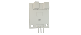
A while back I installed one of these optical endstops that I bought on amazon (3 for $10) in SoM. I chose these particular optical endstop modules because all the parts were located on one side of the circuit board making them easy to mount, there is an on-board LED to indicate when the stop is activated, and they use an LM393 comparator chip to debounce the signal from the opto interruptor. As per usual with low cost Chinese stuff, there was no schematic or data sheet, so I didn't really know if the modules would work with the Duet controller board until I tried one. The Duet supplies 3.3V to the endstop modules, and there have been no problems with the one I used in SoM.
It was really handy to make the Z=0 adjustment in SoM by watching the LED as I made the adjustment, so I used the two endstop modules I had left over in UMMD's X and Y axes.
Here's the CAD model of the opto endstop module.
 |
| The opto endstop module. |
Since I had already modeled the endstop module in CAD for the Z=0 stop for SoM, all I had to do was design the mounts and flags for UMMD. Once they were designed, I printed them in ABS, mounted them on the machine, and tweaked the config file (the mechanical endstops were normally closed, the optical endstops are normally open).
The config file change was simply to convert the endstops from active low to active high by using the S parameters in the M574 endstop definitions:
M574 X2 Y2 S1 ; active high endstops at Xmax and Ymax
M574 Z1 S0 ; active low endstop at Zmin
 |
| The Y axis endstop mounted on the rear corner pulley block. The slotted mount allows the trigger position to be adjusted. The flag is mounted on the X axis pulley block. |
 |
| Here is the Y axis opto endstop on the printer. The flag is pretty thin and fragile, so I may modify the design to make it a little less likely to get broken. |
 |
| Here's the X axis opto endstop on the printer. |
The X axis endstop is mounted on the printer's frame to avoid having to run an extra set of wires to the extruder carriage. That means the Y axis has to be homed before the X axis is homed. The slot in the X axis optical endstop had to be positioned to allow movement in the Y direction before or after after homing, even if the extruder carriage is at the X endstop end of the axis. In other words, the opto interrupter had to be positioned to allow the flag to move into and out of the endstop from either the left side or the front.
I used printed plastic flags to activate the endstops. I have no idea if the pink plastic I used is really opaque at the IR wavelength of the LEDs used in the endstops. It appears to work fine, but I haven't tested precision yet. I may reprint the flags in black or even redesign parts to use metal blades for the flags screwed to printed plastic brackets.
Now that the X and Y optical endstops are in place, I'll try running some prints in which the machine is homed only at the start of the print and then run identical prints where the machine is homed at every layer change like the Markforged machine. It will slow down the prints but if it improves print quality it might be worth the extra time.
Something that remains to be seen is how long the optical endstops last when the chamber is heated to 50C to print ABS. They are being operated from 3.3V supplied by the Duet controller board, which is well within the LM393 voltage and temperature specs, so they may last a long time. The opto interrupters are the big unknown here.
I haven't made an optical Z endstop for UMMD yet because I'm still thinking about how leveling and zeroing the bed will be accomplished- it's a bit different from SoM.
Update 2/19/20:
I replaced the fragile, printed ABS Y axis endstop flag with an aluminum piece made from 3/4" square aluminum tubing.
 |
| Aluminum flag replaces the printed ABS flag for the Y axis endstop. |
UPDATE 3/30/20:
I tested the precision of the X and Y axis optical endstops. Read more about it here.
I also installed an optical endstop in the Z axis and used a differential screw to make fine adjustments to the bed's home position. Read more here.
Finally, I tested the Z axis endstop precision and the accuracy of the differential screw adjuster. Read more here.

No comments:
Post a Comment
Leave comments or a questions here and I'll try to post a response as soon as I can.