Sunday, April 29, 2018

Duet Controller Board Mount

As part of UMMD's conversion from SmoothieBoard to Duet Ethernet, I needed a stand-off mount for the Duet board that would allow me to route wires under the board and allow air flow to help keep it cool.  I found a very accurate Duet Ethernet model by Giuliano Moschini at GrabCAD and imported it into Fusion360, and used it to design the mount for the board.

Underside view of the models.  The posts provide extra support for the board (when you're plugging in cables) without blocking air flow.  You can screw the mount down from the top side using the holes next to the corner posts, or you can screw it down from below using the holes in the corner posts.


Giuliano Moschini's superb CAD model of the Duet board made it very easy to design the mount.


Perfect fit on first attempt.


This was my first-ever PETG print (I know, right?) using Yoyi transparent green filament purchased via Amazon.com.  I measured the diameter in 30 places and it averaged 1.74 mm, with the worst measurement coming in at 1.72 mm.  They seem to have good control of the filament diameter.  The print surface is shiny and the layers are solidly bonded to each other.


This filament glows nicely under UV illumination.  I started printing at 240C/90C and had a tiny bit of stringing, so I dropped the extruder to 235C and the stringing stopped completely.  Printed in 0.2 mm layers, 60 mm/sec, Titan/V6/Volcano with 0.4 mm nozzle, on clean PEI bed.  I did not use a print cooling fan.  The print stayed stuck to the bed and came off easily when the bed cooled.  No lifting even at the sharp corners.


The STEP file for the mount is here.

The STL file is here.

I'll be posting my design for the Panel Due 7i here shortly...


Thursday, April 26, 2018

The Mother of All Print Cooling Fans Revisited: Printable Blower

The biggest problem with the remote print cooling setup I tried here was that the blowers can be a little hard to get or expensive to buy.  At the suggestion of someone on the RepRap forums, I decided to try my hand at designing a printed blower that would mimic the function if not the performance of the CPAP blower.

The heart of the blower is a hard disk drive motor which most people can pull out of an old drive for free.  If you don't have one, someone you know does.  At the makerspace, some of the members work in IT and often bring in boxes full of HDDs to be scrapped.  They're mostly after the aluminum chassis to be melted down for casting, and the magnets.  I like to grab the bearings from the head positioning lever, and I grabbed a few motors for just-in-case.  It looks like that was a good idea!

I made some measurements and created a model of the motor first, then the impeller, and finally the housing.  This isn't a final final design- more of a proof of concept.  I'll be updating the design to some final form to fit the CPAP hose, etc., in the near future.  I want to experiment with a straight-through type design where the exit port will be on the "bottom" of the housing (should be easier to print).

Printed blower with the cover in place, held on with a few pieces of aluminum tape for testing.  The blower is 68mm in diameter and 41 mm high.


Cover off showing the impeller, held on the motor with 3 screws.  The impeller is 60 mm in diameter, and rotates CCW.  As it spins, air drawn into the center of the impeller is flung outward by the vanes, and goes down into the base where it is directed out through the exit port.


HDD motor mounts in the base using 3 screws.


Base has posts to mount the motor, and wires are fed through a hole in the side.  The posts are probably not very aerodynamic, so I'll look for ways to change the design for a little better performance.  It might be better to take the wires out through the bottom surface for the same reason.


3D printed blower for remote print cooling in a 3D printer from Mark Rehorst on Vimeo.


Ebay is littered with cheap drivers for HDD motors.

Update:  I reworked the design, made it much more practical, and it moves a little more air, too.  It's still not as powerful as the CPAP blower, but I suspect that's mostly because of the motor speed.

The new design prints in 4 pieces, the 80mm diameter impeller, top bottom covers, and the 22 mm diameter exhaust tube.  I decided to make the tube a separate piece so that it would print in very high quality.  It also allows the possibility for different sized tubes to be mounted on the same blower.

The assembled blower.

All four pieces: the base and top covers, the exhaust tube, and the impeller.  No support material is needed for any of them.

All four pieces print without support material.  I printed the impeller in 100 um layers, and the other pieces at 200 um.  I used PETG for the impeller and ABS for the housing, but since none of it gets warm, you could really use just about any materials you like.

The bottom side of the base (left) has slots for routing the motor wires.


I added mounting holes on all six sides of the housing, and some slots on the bottom for routing motor wires in case you screw the bottom of the blower down to a flat surface.

The output tube is 22 mm in diameter to match the rubber end of the CPAP hose.

The exhaust tube fits into slots in the top and bottom covers.  There are also bosses to ensure that everything self aligns when you assemble it.  The top and bottom covers are held together with plastic anchor screws.

While the box fits together tightly, it's a 3D print, so there's no guarantee that it's air tight.  It's probably a good idea to run a strip of tape around the seam in the box where the top and bottom covers meet to reduce any losses that may occur via that route.

How does it work?  See for yourself:


You can download the CAD files or just export the STLs here.

You can download the STEP file here...

Update  5/6/18:  I kept asking myself "why doesn't this thing move as much air as the CPAP blower?", so I did a couple basic tests.  Though I don't have a tachometer to measure the speed, setting them up side by side the answer was obvious.  The CPAP blower spins MUCH faster.  Another thing I noticed was that the clearance between the outer edge of the impeller and the housing in the CPAP blower was about 4 mm.  My printed housing was 83 mm in diameter and the impeller was 80 mm, so I designed and printed a 75 mm impeller to allow more clearance.  This impeller has 9 vanes instead of 12, which works nicely with the spacing of the 3 screw holes.

When I tested it again it didn't seem to move any more air.

That got me thinking- the CPAP motor is rated for 25W and when I'm running at full output, it's using about 12W to move the air (OK, some is moving the air and some is heating the motor).  The HDD motor is designed for low power- maybe 5 or 6W at 12V, so of course it isn't going to move the same amount of air as the 25W CPAP blower.  It's turning slower and it doesn't have the same power available to do the extra work needed to spin faster against the resistance of the air.

So, figuring that anyone who wants to use something like this for a print cooler for a 3D printer is probably going to have a 24V supply in the printer, I tried connecting it to a 24V power supply:

Printed blower with HDD motor running at 24V from Mark Rehorst on Vimeo.

Woohoo!  Look at that!

I decided to check the current:


Yup, about 1A which works out to about 24W.  The CPAP blower uses about 12W and it moves about the same amount of air.

I got out my handy-dandy IR thermometer and pointed it at the motor in the bottom of the case and it was reading about 60C after about 15 minutes of operation.  That's probably a bit excessive for a HDD motor and it probably won't last long at that temperature.  And you definitely shouldn't print the blower using PLA if you're going to run a HDD motor at that kind of power input.  Of course, in a normal 3D printer you don't need nearly that sort of air flow so it should be OK to run it for print cooling from a 24V supply.

I think this could be made to move air like the CPAP blower by using a BLDC motor used in RC cars and airplanes.  The CPAP uses a 4 pole motor rated for about 22k rpm and 25W.  That's about 2000 rpm/V.

In the RC world, they generally don't talk about voltage.  They think in terms of lithium battery cells connected in series.  Each cell produces 3.7V, so the closest thing to a 12V motor will be a "4S" (4 cells in series- 14.8V) motor.  So what we want is a 4S motor, preferably one that isn't rated for much more than 25W, which is similar to the CPAP motor spec.

The place to look for cheap brushless DC motors with similar ratings to the CPAP motor is RC hobby suppliers.  But you have to be careful when selecting an RC type motor is that they are often rated for huge amount of power in very small motors.  That means the winding resistance and inductance are. very low and they may take huge current (and run hot).  Those motors are usually kept cool by the prop-wash that is blowing over them whenever they operate.  The centrifugal compressor/blower I'm making copies the CPAP blower and puts the motor in the box with all the swirling air, so the motor should stay nice and cool.  Even at that, you don't want a motor that's going to suck too much current and you don't want it to burn up if you're running it from a 12V power supply.

If you're using this type of blower for a print cooler, it's never going to operate at full output, which means lower voltage motor should be OK even if you run the driver from a 12V supply.

A quick check at Hobbyking finds dozens of cheap brushless motors rated for 2000 rpm/V (2000kv in RC hobbyist lingo) or more, but only a few 4S rated motors.  If you use a lower voltage motor it will work OK, but if the driver ever fails it may burn up the motor.

Here's a promising motor for $7.42.  It's a 3100kv, 3S motor rated for 59W.  It should work fine from a 12V supply which will theoretically push it over 36k rpm, but again, we won't be running it nearly that fast for print cooling (PWM will keep the power and speed down) so it should work fine.  It's only 13mm in diameter and it weighs 10g!

UPDATE 4/1/20:


There's been a lot of interest in this post since the COVID-19 epidemic became a thing.  For anyone who is interested in trying something like this and doesn't know how to go about copying the curves in the blower impeller, I did a blog post that includes the technique I used here.


Monday, April 23, 2018

UMMD: Migrating from SmoothieBoard to Duet Ethernet, Part 2

Configuration

Part of the conversion from SmoothieBoard to Duet involves deciding what has to connect to what and then configuring the board appropriately.

This table lists which items in UMMD will connect to which I/Os on the Duet board:

UMMD Duet connection Note
A motor Drive 0 part of XY stage
B motor Drive 1 part of XY stage
Z motor Drive 2 Rino motor
extruder motor Drive 3
X endstop X stop switch located at Xmax
Y endstop Y stop switch located at Ymax
Z min endstop Z stop Z=0 switch
Z max endstop E1 stop
bed thermistor Thermistor 0
hotend thermistor Thermistor E0
chamber thermistor Thermistor E1
bed heater Heated Bed drives SSR
extruder heater E0 heater
chamber heater E1 heater drives SSR
extruder cooling fan Fan 0 will leave off until hotend temperature reaches 45C
print cooling fan Fan 1 PWM
chamber heater fan Fan 2 not sure about this

The Duet board wiring diagram is located here.

The Zmax switch located at the bottom of UMMD's Z axis prevents the high torque drive from trying to move the bed lower than the bottom of the axis, which might cause some damage to the belts or pulleys.  I'm not sure how I'm going to handle that yet.

The line powered 500W chamber heater has a fan to prevent the temperature of the heater bar from getting too high and to circulate the warm air inside the chamber.  Right now the fan is driven by the signal that drives the SSR switching power to the heater, which uses PWM under PID control.  It might be better to operate the 24V fan at some constant, but <100% duty cycle (not trying to create a tempest, just stir the air in the enclosure a bit), whenever the heater is in use as opposed to switching the fan on and off with the heater bar.

UMMD uses a 24V, 200W, fanless power supply, and has two dc-dc converters that power white and UV LEDs.  Those LEDs are switched manually with a DPDT switch.  There is currently a fan that blows air over the SmoothieBoard and the power supply to keep things cool.  None of that will affect the configuration of the Duet board.

I have two options for the print cooling fan- the small squirrel cage blower that mounts on the extruder carriage and the remote CPAP blower that is powered by its own driver board under PWM drive from the controller.  Whichever I settle on will use one of the PWM fan outputs.

Electronics Considerations


UMMD has electronics mounted on the top of the enclosure, at eye level, so I don't have to bend over when working on the machine.  Most of the wiring has to connect to the XY stage on the printer, so putting the controller on top keeps most of the wires shorter.  With the Duet conversion, I may move the 117VAC fuses and distribution, 24V power supply, and bed heater SSR to the bottom of the printer.  That will considerably reduce clutter on the top of the machine.  The power supply and SSR are pretty reliable so I shouldn't have to do a lot of work involving those.

The biggest problem is deciding how to mount the LCD panel.  The easiest thing is to just stand it upright on the top front of the printer and be done with it.  That would be reasonably safe when transporting the printer, but doesn't address the problem of curious fingers messing with it at events like Maker Faires.  The Panel Due doesn't currently support a PIN for access (though I posted a request for it on the forum), so covering it is the best way to control access.

Panel Due details are located here, but more up-to-date info appears to be here.

Getting It Talking On the Network and Update Firmware


It took a bit of searching (the web site has a lot if info, but isn't optimally organized), but I found out how to get the Duet board onto my network so I could take a look at the web control interface and configure it for UMMD's hardware.  Here is the procedure.

I powered the board using a USB cable and connected the network cable and followed the procedure, but couldn't get the web interface to show up in my browser because there was another device on my network that had the same IP address that the Duet was reporting.

My Duet board was configured with an IP address of 192.168.1.14 (in the config.g file on the Duet uSD card), and that happened to already be assigned to a device on my network.  Once I figured out what was going on I edited the config.g file and set the assignment to 0.0.0.0 so that my router would assign an unused IP address.

After that the web control was accessible through my browser.

Next step- update firmware and web server.  I downloaded the firmware (DuetEthernetFirmware.bin) and the web server (DuetWebControl.zip)here, and then installed them, firmware first, then the web server, via the web control page in my browser.  Both updated with no trouble at all to versions 1.21

Configuring

The first thing you see after connecting to the web control is that the firmware wants you to configure your printer.  I went to the configurator and did that based on the contents of the table, above.  There were a few things I had to guess at, such as motor rotation directions, so we'll see when I actually hook the printer to the board what I actually end up with.

Connecting Panel Due 7i and Updating Its Firmware


I took out the supplied 4 wire serial cable and hooked the LCD panel to the Duet board, then connected the USB cable to the Duet board to power things up and the Panel Due worked fine without any messing around.  The setup screen indicated that the firmware was version 1.17, and I checked the website here and found that there is a newer version of the firmware available.

I updated the firmware and added a custom splash screen.  You have to gather things in different places, but if I could do it, you can too.

Get latest firmware here
Get instructions for flashing the firmware via USB here
Get Bossa (used to flash the new firmware)here

Adding a Splash Screen (optional)


Create an 800x480 x 24 bit per pixel bmp file in whatever graphics program you like.
Get the compression program here
Follow procedure at bottom of page here to compress the splashscreen file and append it to the firmware file.

Finally, burn the new firmware using Bossa.  I found the GUI for Bossa worked fine on my Win 10 machine with a QHD display.

Custom Splash Screen for Panel Due from Mark Rehorst on Vimeo.


Local Connection via Network Cable


A day or two after all the above was done, I realized that when I go to Maker Faires and other public venues, there isn't usually a wired network to connect to.  Also, there are no wired ethernet drops in my basement workshop or the garage.  In planning the new electronics enclosure for the Duet and Panel Due, I couldn't come up with an easy means of accessing the uSD cards in either device- the Duet will be too deeply buried in the enclosure with too many cables in the way, and the position of the uSD card slot on the bottom edge of Panel Due makes it a little difficult for me to access on my machine, so I need to be able to connect a computer directly to the Duet board to do things like change the machine's configuration and upload gcode files to print.

The Duet board has both USB and ethernet connections.  In order to use the USB port for anything other than powering the board while testing, you need the driver files which you get here.  Grab the file called "DuetWindowsDriverFiles.zip".  Install in your Windows PC and I assume you're good to go.  I'm not a huge fan of USB connections, so I prefer to use the ethernet connection, even if file transfer is a bit slower.

I did a little digging and it turns out getting a computer to talk directly to another device over a network port (no routers or switches) is pretty easy to do.  I'm no networking expert, so if I can figure it out, so can you.  I started with a search at the Duet forums, and followed along.  I am using an Acer netbook computer (there's still plenty of life left in old computers!) running Linux Mint.

The first thing I did was to edit the config.g file on the Duet's uSD card.  I commented out the line that said "M552 P0.0.0.0 S1" which enable networking and tells it to get an IP address via DHCP, and replaced it with "M552 P192.168.1.3 S1" which forces it to use IP address 192.168.1.3.

I put the uSD card back into the Duet board and connected it to the netbook via a short ethernet cable, powered up the Duet board with a USB cable, and powered on the netbook.  Some older computers require a crossover cable to swap Tx and Rx connections to allow them to do this sort of thing, but my 2007 era netbook is new enough that it automatically switches, so a regular network cable worked just fine.

In the netbook I went into the network configuration and set up a new wired connection using address 192.168.1.2, netmask 255.255.255.0, and gateway 192.168.1.1, DNS servers 1.1.1.1, search domains nameserver, 1.1.1.1.  The DNS server stuff shouldn't matter, but I had to enter something because the network manager wouldn't let me save the connection without putting some values in there.

So now both the Duet board and the computer are in the same subnet and assigned sequential addresses.  I verified the connection by opening a terminal and entering "sudo nmap -sn 192.168.1.0/24" and it indicated that there was a connection to the Duet board at 192.168.1.3.  Then I opened a web browser and entered 192.168.1.3 and it brought up the Duet Web Control pages.

I tried uploading a 30 MB gcode file from the computer to the Duet board and it ran at about 500-600 kB/s.  It took about a minute- not super fast, but fast enough.


Next up: Electronics enclosure

Sunday, April 22, 2018

UMMD: Migrating From Smoothieboard to Duet Ethernet, Part 1

Back when I started designing and building my own 3D printers about 6 years ago, Arduino/RAMPS was all there was to control a 3D printer.  Every configuration change required editing multiple source code files then recompiling the firmware.

About 4 years ago I switched from the 8 bit A/R setup to a 32 bit SmoothieBoard controller.  It was a huge improvement in usability, reliability, and ease of reconfiguring the machine.  There was no need to compile firmware- configuration changes were as easy as editing a single text file containing all variables, and rebooting the board.  I do a lot of experimentation in my printers with different extruders, different drive mechanisms, etc., so it's really been nice to be able to make changes quickly.  Motor driver chips were soldered to the board and adequately heatsinked, so there was no more blowing up crappy little motor driver modules.  Motor currents were set in the config file, so there was no trying to adjust microscopic, easily broken pots.

Every once in a while I try to repair a printer at the makerspace that uses an 8 bit controller and I am reminded how far things have come.  A recent extruder upgrade to a machine at the makerspace had me hunting for obsolete Arduino IDE, obsolete plugins, obsolete USB driver, and obsolete firmware, all so I could change the steps/mm in the extruder.  Ugh!

Duet controller boards came out a few years ago and have really come a long way, quickly.  Besides a lot of advanced programming, the newest boards use super quiet TMC motor driver chips, and favor networking over USB interface.

I've been unhappy with the way UMMDs electronics spoils the appearance of the machine from day one, but it was all working and rewiring a 3D printer is a major undertaking, so I've adopted an "if it ain't broke don't fix it" attitude.

UMMD's electronics, including an experimental remote print cooling blower (the sort of thing I need to be able to reconfigure for).  Ugly but functional.  The basket allows air flow and visual inspection of everything.

Another view.  The upper front cover panel slides down into the slots in the frame members, then the white top cover slides forward to seal the top edge and prevent the top front cover from opening.  It's useful at Maker Faires where curious fingers tend to push buttons and open things they shouldn't.


I haven't had enough motivation try out a Duet until Tony Lock at Think3DPrint3D sent me a Duet Ethernet controller board with a Panel Due 7i touch screen interface (Thank you very much!).  I just had more foot surgery and I'm stuck at home for the next three weeks, so I thought it's a great time to put the Duet into UMMD.

This will be the first in a series of blog posts on the conversion.

First impressions


The connectors on the Duet board are better than those on the SmoothieBoard.  They are designed for a little heavier gauge wire, they are polarized, and they snap into position and it takes some effort to dislodge them.  The board also came with crimp ferrules for use on wires going into the screw terminals.  Nice!  The main power input and bed heater connections are super beefy screw terminals.

One of the things I liked about the SmoothieBoard over the Arduino/RAMPS set up I started with about 6 years ago was that all the connectors were brought out to the edges of the board.  That made it much easier to lay out the wires and cool the circuit board.  The Duet has so many connectors, including a wide expansion header, there isn't room for all of them at the edges of the board.  The ability to expand the electronics is probably worth the extra clutter when all the cables are in place.

The SmoothieBoard has always had small and oddly placed mounting holes with little clearance from adjacent components, making it a little tricky to mount the board.  The Duet and Panel Due boards both have regular hole spacing and plenty of clearance around the holes for screw heads and standoffs.  One of the first things I did was locate a CAD model of the Duet board so I could plan the enclosure.  There was no Panel Due 7i CAD model to be found, so I made my own in Fusion360.

The Duet board has motor drivers that interpolate the 16:1 ustepping to 256:1 to make the motors run quietly.  I'm looking forward to that, and will post "before" and "after" videos of UMMD running under smoothie drive and Duet.

The Panel Due is a huge improvement over the LCD module I've been using for the SmoothieBoard.  It has much more control capability, however, the uSD card slot is located along the bottom edge of the board which may make it difficult to use.  Also, it doesn't play well with the PT100 daughterboard in case you use one of those (and I plan to).  The designers really put the emphasis on network control and I may have to start using it whether I like it or not.

Next post: Firmware updates and configuring


Saturday, April 21, 2018

Designing A Low Cost, Printable Worm Gear Reducer For Belt Lifted 3D Printer Z Axes

Warning

This is a project I started to see if the Rino worm drive used in UMMD could be replaced with a lower cost alternative made using a printed gearbox and some cheap, sintered gears from China.  The project was a failure, but I wrote all the stuff below as I worked on it, and there may be some value in that, so rather than ignore the whole thing, I'm posting it with this warning.  If you're not interested in the process, skip to the bottom of the post to see what went wrong.

If you never fail, you never learn...

Intro


Belt driven Z axes offer some advantages over screw driven Z axes in 3D printers.  Unlike very long or bent screws, they do not produce any lateral forces that can cause the bed to wobble and leave defects in the prints.  Belts cost less than screws.  Belt lifted Z axes can be made to any length needed, a benefit in tall printers.

There are two main reasons why belt lifted Z axes aren't more common in 3D printers.  First, many people think that belt stretch may degrade print accuracy.  Second, a belt lifted Z axis requires some means to prevent the bed from dropping like a rock when power to the Z axis motor is cut.

Both of those concerns were addressed in the design of Ultra MegaMax Dominator (UMMD), my coreXY printer that includes a belt lifted Z axis.  After construction, belt stretch was measured at 42 um/kg print mass (using 10 mm wide steel core belts) and its effect on print accuracy calculated.  The conclusion: belt stretch is inconsequential.  The bed-drop on power-off problem was solved using an  industrial surplus OnDrives Rino 30:1 worm gear reducer.  It works perfectly, though I made an poor choice in the drive pulleys.  More on that later.

The only problem with the belt lifted Z axis in UMMD was the cost of using the Rino worm gear reducer.  That part, including NEMA-23 motor (overkill for lifting the bed in a 3D printer), and keyed 8mm shaft cost $138 all-in.  It's an elegant solution to the bed drop problem, but Ouch!

This post is about a less expensive way to make a worm gear drive.  The new design duplicates and even improves on the function of the Rino for about $40 which includes the cost of the gears, bearings, shaft, and motor.

Parts Selection

I considered the following when selecting the parts to use:

1) NEMA-17 motor, common and cheap
2) use common bearings and shafts
3) gear ratio of 30-1 or higher to ensure adequate full-step resolution and lifting force
4) gears fit motor and shafts without couplers
5) use common pulleys and belts
6) full step resolution of 50-100 steps/mm


Motor:

In UMMD, the motor supplied with the Rino worm drive was rated for 164 oz-in holding torque at 1.8A.  It operates at 1A in UMMD, so the actual holding torque is probably a little less than 100 oz-in, yet it is more than enough to lift the 3.5 kg bed and support assembly plus 4 kg of print mass and run it up and down at 20 mm/sec.

NEMA-17 motors rated up to 100 oz-in are readily available, and they are smaller and usually cheaper than NEMA-23 motors, so I chose to design the worm gear mechanism to use a NEMA-17 motor.  

NEMA-17 motors normally have 5 mm diameter shafts, so I needed to find a worm gear set that had a 5 mm bore worm gear so that it wouldn't need any adapters or shaft couplers.

I used a 42BYGH610, 40 mm long, 200 step/rev, 1.2A, NEMA-17 motor that I had in my parts collection- it doesn't take a big motor to lift a few kgs.  That motor is rated for 3 kg cm (about 42 oz-in) holding torque.  The 40:1 gears will multiply that torque up to about 120 kg cm.  That sounds impressive, but torque drops off with speed and current, and the motor is going to have to run fast to move the bed at a reasonable speed.


Torque curve from the motor's data sheet.  PPS in the X axis is equivalent to full steps (?), so divide by 200 to get revs/sec.


Shaft:

The Rino used an 8 mm keyed shaft.  The 8 mm part was fine- it is commonly used in 3D printers anyway, and as a result, there are a lot of bearings and pulleys with 8 mm bore readily available, but the key had to go.  The disc gear needed to have an 8 mm bore and use set screws to hold it on the shaft.

Gears:

Basic gear specs to be met: 5 mm bore worm gear, 8 mm bore disc gear, both gears had to use set screws (no keys!), and a gear ratio of at least 30:1 to ensure adequate resolution and lifting power.  After digging through the worm gear set listings on ali-express, I found a 40:1 set that had the requisite 5 mm bore worm gear and 8 mm bore disc gear, both with grub screws for easy attachment to a 5 mm motor shaft and 8 mm unkeyed output shaft.

Bearings

UMMD used 8 mm self-aligning pillow blocks at the ends of the output shaft.  There was no reason to use anything different, so I used the same parts.  I also needed some 8 mm bearings for the gearbox, so I used F608zz bearings like the ones I used in UMMD's XY stage to make the pulleys.  The flanges keep the bearings in position inside the gearbox- more on that later.

Belt

UMMD used 3 mm pitch HTD 3M belt, but 2 mm pitch GT2 belt is more common, as are the pulleys for it, so this system is designed to use GT2 belt, either steel or glass core.  Of course it can easily be switched to any other belt pitch simply by changing the pulleys.  I prefer to use 9-10 mm wide belt as it will stretch less than 6 mm belt under the same load, and doesn't cost much more.  Pulleys for either width are readily available.

Pulleys

Using 2 mm pitch GT2 belts means 2 mm pitch GT2 drive pulleys, and they need 8 mm bore to fit the 8 mm output shaft from the gearbox.  See below for the calculations for the number of teeth.  The flanged pulleys at the top of the Z axis are made from pairs of F608zz bearings mounted on flat plates with shoulder screws for axles.

The combo of motor steps per rev, gear reduction ratio, belt pitch, and pulley teeth determine the full step resolution of the Z axis.  Having full-step resolution equal to a nice, round number avoids math errors in the controller and current errors in the motor driver chip that can lead to Z axis print defects as well as making print layer thickness selection convenient.  I used a typical 200 step/rev motor, 40:1 gear reduction, so now I had to figure out how many teeth the pulleys should have to get a good full step resolution value for the drive.

UMMD used a 200 step per rev motor, 16:1 ustepping, a 30:1 gear reduction drive, 3mm pitch belt and 36 tooth pulleys.  That was an unfortunate choice for the pulley, (see redux in column 3), because it resulted in full step resolution at 0.018 mm intervals.  This spreadsheet calculates the full and microstep resolution of belt lifted Z axes and the full step layer thicknesses available.


printable NEMA-17
descriptionUMMD originalUMMD reduxworm gear driveunits
motor200200200steps/rev
ustepping ratio161616:1
gear ratio303040:1
belt pitch332mm
pulley teeth364040
full step resolution55.5555555650100steps/mm
full step resolution0.0180.020.01mm/step
ustep resolution888.88888898001600usteps/mm
ustep resolution0.0011250.001250.000625mm/ustep
full stepslayer thicknesslayer thicknesslayer thickness
10.0180.020.01
20.0360.040.02
30.0540.060.03
40.0720.080.04
50.090.10.05
60.1080.120.06
70.1260.140.07
80.1440.160.08
90.1620.180.09
100.180.20.1
110.1980.220.11
120.2160.240.12
13


Notice the nice 0.01 mm full step resolution in the 4th column.  That means any multiple of 0.01 mm can be used for print layer thickness.  Compare that to column 2, the original UMMD Z-axis set-up.  The switch to 40:1 gears and 2 mm pitch belt is a big improvement.

Potential sources of error


Imperfect gears will lead to periodic print defects.  If the disc gear is imperfect, print flaws will show up and repeat at 80 mm intervals.  If the worm gear is imperfect, repetitive print flaws will show up at 2 mm intervals.  See photos of test prints below...

Gearbox Design


The whole Z axis is going to consist of the gearbox, output shaft, and pulley(s), plus the frame and guide rails/linear guides, and bed (or X axis) support assembly.  The belt(s) will have to be in a position that allows a clamp attached to the linear bearing block(s) to grab it.

UMMD's Z axis with the Rino worm drive assembly at the bottom of the Z axis and two belts lifting the bed assembly.  Other configurations, including lifting the X axis in an i3 type printer, are possible using a similar setup, probably inverted.


When designing something like this, a good place to start is by making 3D models of all the hardware and assemble them in CAD, then design the box to hold them.

These are the mechanical parts that are not printed, excluding screws to fasten things together.  There are two, 1.5 mm thick nylon washers between the F608zz bearings and the disc gear that are not visible.


There are some critical dimensions and relationships that have to be maintained in the final printed part(s).  For example, the F608zz (or RF2280HH) bearings are going to have to be accurately aligned on the same axis and they have to fit into holes in the printed plastic.  The distance between the flanges is:


bearing flange thickness:1.5mm
washer thickness:1.5mm
disc gear thickness:20.2mm
washer thickness:1.5mm
bearing flange thickness:1.5mm
total:26.2mm


Other critical dimensions include the spacing between the two gears which translates to the spacing between the motor shaft and the output shaft, and the motor hole spacing.

aeProduct.getSubject()
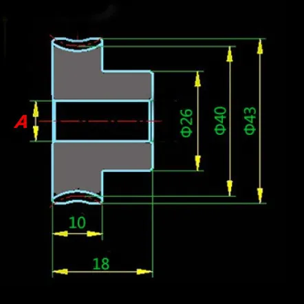
This is the disc gear drawing from the aliexpress page, with 8mm bore and 20 mm distance from the center of the bore to the worm gear contact point.  Unfortunately, the gear I received does not match this drawing!


aeProduct.getSubject()
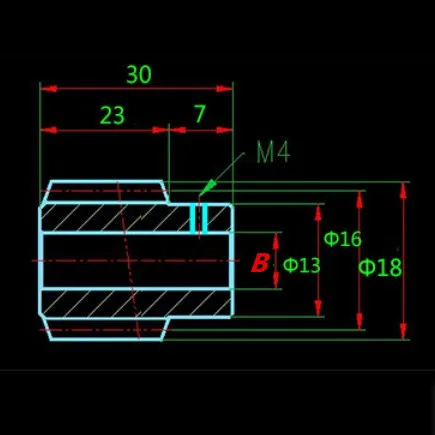
Mislabeled worm gear drawing- the text says bore is 5 mm, not 13 mm, and the pitch diameter is 16 mm, so it's 8mm from the center of the bore to the disc gear contact point.  The gear I received did not match this drawing.

The first thing I did when I received the gears was make measurements to confirm their dimensions.  Surprise!  The gears didn't match the drawings on the ali-express order page.  I made models of the gears that were shipped, and drawings with critical dimensions from the model.  Here is the dimensioned worm gear drawing and here is the disc gear drawing.

The ideal axle center to axle center spacing is 29 mm.  One of my early prototypes used 29 mm spacing and when I assembled everything, the gears were binding, so I moved them apart a little in the next couple prototypes.  The final design spaces them at 29.35 mm apart which allows for a tiny bit of rotational play (I can hear a click but the movement is so small I can't see or feel it).  The rotational play won't matter in operation because the mass of the bed assembly will keep the gears fully engaged on one side at all times.  There should be no backlash.

The next step is to design a printable box to enclose the gears and bearings while maintaining those critical relationships.

When you design a printed part that is going to be subjected to mechanical force such as belt tension, if you don't want it to flex much you have to keep the plastic bulky.  For example, a lot of designs for 3D printed motor mounts use plastic shaped like L brackets, sometimes with a little reinforcing webbing (examples:  https://www.thingiverse.com/thing:715526 and https://www.thingiverse.com/thing:175413).  That sort of thing might be rigid enough if it's made of steel or even aluminum, but plastic?  As soon as you apply belt tension, the mount is going to flex/twist.  I prefer to print such parts thick and heavy so they won't flex (as much).  I think of the design in terms of starting from a solid block and removing as little plastic as possible to accommodate the other parts.

Two styles of printed plastic motor mount.  Which do you think will flex more when belt tension is applied?

I used the green type design technique for this gearbox.  I started with a solid block of plastic and removed just enough material to accommodate the parts that have to fit inside or attach to it.

If the print has the holes for the bearings printed in the vertical walls, the outer surface of the holes will be made of stacked layers, and will be rough, especially at the top and bottom, because of the nature of 3D printing in layers.  That's going to make it hard to ensure that the bearings will be accurately aligned with each other.  It is better to print the holes for the bearings flat on the printer's bed.


Early prototype gearbox printed as a single piece with holes for bearings in vertical walls.  Note rough areas at top (and not visible, bottom) of the bearing mounting hole

Bearing inserted into hole.  Will it line up with the bearing on the other side of the box?  Maybe...

Prototype gearbox with bearing mounting hole printed flat on the printer's bed, taking advantage of the much higher precision and accuracy of the XY mechanism.  Bosses around screw holes help align the halves of the box when assembling.


Bearing inserted into mounting hole.  Will it line up with the bearing on the other side?  Sure!

I made a prototype using a single printed piece (the red one in the photos, above) but it had a couple problems.  The bearing holes that require critical alignment were "iffy" because of the way the print layers stack and the rough surfaces at the bottom and top of the holes.  It would also be difficult to assemble because of the tight space for mounting the bearings, washers, and disc gear.

The next couple prototypes were made in two pieces with the bearing mounting holes printed flat on the bed.  I added bosses to align the two sides of the box and ensure alignment of the gears and bearings when the part was assembled.  The bosses surround the screws that hold the halves of the box together.  When you design two parts to be screwed together like this, the piece where the screw will be inserted will have a loose fit hole for the screw and the other piece will be a tight fit where the screw will roll its threads into the plastic.  The boss will go on the part where the screws are inserted and the receptacle will go on the part into which that the screw will cut threads.  If you do it the other way, when you drive in the screw, the relatively thin plastic boss is liable to break off.


Bosses (the collar surrounding the screw) in one half of the gearbox align it with the other half that has matching receptacles.


The screw hole in the boss allows the screw to pass freely.  The hole in the receptacle gets grabbed by the screw's threads.  Don't do it the other way- the boss will break off when the screw starts grabbing it.


When designing prints to fit real world parts like bearings, you have to account for the smaller printed hole sizes that FDM printing produces.  In my printer, experience has taught me to make holes 0.35 mm larger than the object that has to fit into the hole, so for example, the bearings are 22 mm in diameter so I designed the printed gearbox with 22.35 mm diameter holes.  The bearings fit into the printed box halves tightly.


Assembly- put the worm on the motor shaft, and put the disc gear, bearings, and washers on the 8mm output shaft- don't forget to put Lock-Tite on the set screws!  Screw the "A" side (on the left) of the box to the motor, insert the output shaft assembly, put the "B" side of the box (right) on the shaft and screw it to the motor, then screw the two halves of the box together.


The two piece gearbox was a much easier to assemble option, but you have to follow a specific sequence because the over-sized disc gear mounting collar interferes with tool access to mount the motor.

The design of the Z axis, and dimensions of common frame materials have to be considered when figuring out how to mount the gearbox.


Fusion360 sure can do some nice rendering...


This is the "A" side of the gearbox that gets screwed to the motor as a second assembly step (after first mounting the worm gear on the motor shaft).


The "B" side of the gearbox, on the right, gets mounted after the bearings, shaft, disc gear and washers are put in place.  Once the whole thing is assembled you can bolt it to the t-slot using a single bolt.


Performance tests


The design above is a generic design that is intended for putting into new printer designs.  I wanted to test the performance of the gearbox and thought about how to build up a test jig and came to the conclusion that the easiest thing to do would be to replace the Rino in UMMD and test it in the printer, so I designed modified the generic version to be an almost drop-in replacement for the Rino.  I also switched to GT2 belt and since the drive pulley diameter changed I had to reprint the spacers for the pillow blocks and the belt clamps.  After all that, I installed it and ran some tests.

The first test was just to see if it could handle the same sort of load the Rino had been able to lift, so after tweaking the firmware for 1600 usteps/mm and reducing the speed to 10 mm/sec (it stalled at 20 mm/sec), I checked the lifting capability and belt stretch:

First test of printed worm gear box in UMMD from Mark Rehorst on Vimeo.


Belt stretch test prep: the gauge is bolted to the printer's frame and zeroed on the bed.


1.25 kg load, about 50 um stretch.


2.5 kg load, about 130 um stretch


3.75 kg load- about 210 um stretch


This video shows some stretch and precision/accuracy tests:

UMMD 40:1 worm drive precision testing and belt stretch under load from Mark Rehorst on Vimeo.

Notice that when I moved the Z axis in 1 mm steps every other number looked about right while those in between were a little off.  Hmmmmm...

Print test

I prepared a test print to see how well the new Z axis drive would work.  I printed in 100 um layers and this was the result:


This is not wobble.  This is banding.  The difference is that wobble is a misregistration of the print layers caused by inaccuracy of the bed to nozzle position that can be caused by unwanted lateral movement of the bed or the extruder nozzle.  If you have wobble, one side of the print will bulge and the opposite side will be concave.  In banding like this, the layers become too thin causing the extruded plastic to squish out along the sides of the nozzle creating bulges that go all the way around the print and even in the infill ribbing.


A closer look at the layers and the bulging.  The bulges repeat every 2 mm.  The worm gear rotates once for every 2 mm of Z axis motion, so there seems to be a problem with the worm gear.  The disc gear rotates once for every 80 mm of Z axis motion, so a much taller print would reveal any defects in the disc gear.


165 mm tall print in 0.25 mm layers.  I don't see any artifacts that repeat at 80 mm intervals, and the 2mm ribbing is a little better than the 0.1 mm layer print, but still not good.


Error

The worm gear rotates once for every 2 mm of Z axis movement, so the banding points to the worm gear as the source of error.  The error may be in the tooth surface in which a divot will cause the disc gear to not rotate as much as it should resulting in smaller Z displacement.  Or it could be the bore of the worm gear is off-center.

I stepped the Z axis in 0.1 mm steps, recorded and plotted the error:


A single tooth of the worm gear engages the disc gear, so it may be that shifting the worm gear along the motor shaft would allow one to find a tooth that is better (or they might be worse).

Conclusion


These particular gears provide a great way to increase motor lifting power but they are just not good enough for the micron level positioning needed in a printer's Z axis, unless you're going to print in very thick layers.  Other gears are available, and I may revisit this topic at some time in the future if I run into a source of inexpensive, high quality gears.  In the meantime, I put the Rino back into the printer but changed to 40 tooth pulleys on the 3 mm pitch belt, yielding resolution of 50 full steps per mm.  Changing the pulleys required a change to the belt clamp design and the upper pulley plates.