Arrakis 2.0 made it's public debut at the Maker Faire Milwaukee on October 22, 2022, and got a nice write-up in Make magazine.
I liked Arrakis, but found some problems after living with it for a while.
- The bottom of the sandbox was made of 1/4" Baltic birch plywood covered with a sheet of black EPDM rubber to keep the ball-rolling noise down. Most of the time it was fine, but with some patterns where the ball passes over the same area repeatedly, the sand would be pushed away revealing the black rubber. I didn't like that so much.
- An even bigger problem was that the plywood warped depending on the weather, enough to close the air gap and the magnet would drag on the underside of the sandbox, making noise and producing wood dust. I put a lot of effort into making it run quietly, so this really bugged me.
- Running the table at high speed causes the ball to throw the sand, so in the original design I separated the top and bottom as much as possible so I wouldn't have to keep cleaning sand off the underside of the glass top cover. It worked, but I decided that the bottom of the sandbox, where the drawings appear, was just too far below the top cover, requiring uncomfortable seating to view the drawings.
- In packing up for the Maker Faire I found lots of PTFE dust in the mechanism- PTFE isn't ideal for sliding bearings for this reason.
In the interest of keeping this post relatively short, I won't go into too much detail, but will use lots of photos to show what changed.
 |
Arrakis 2.0
Iced latte! See! I really use it as a coffee table. |
Sandbox redesign and build
First, the legs were lengthened to raise the XY mechanism higher. Then I built a 45 mm t-slot frame to hold a sheet of 4.7 mm thick tempered glass (same size as the top cover!) and covered the glass with cloth-backed white vinyl. LED strips were mounted in aluminum C channel stock that was screwed to plastic strips that fit into the t-slots in the sandbox bottom frame. A decorative frame, made from prefinished white polystyrene molding, drops into the sandbox on top of the LED C channels. Side panels are made from 1x8" wood and simply bolted to the t-slot frame using t-nuts and countersunk M6 flat head screws.
 |
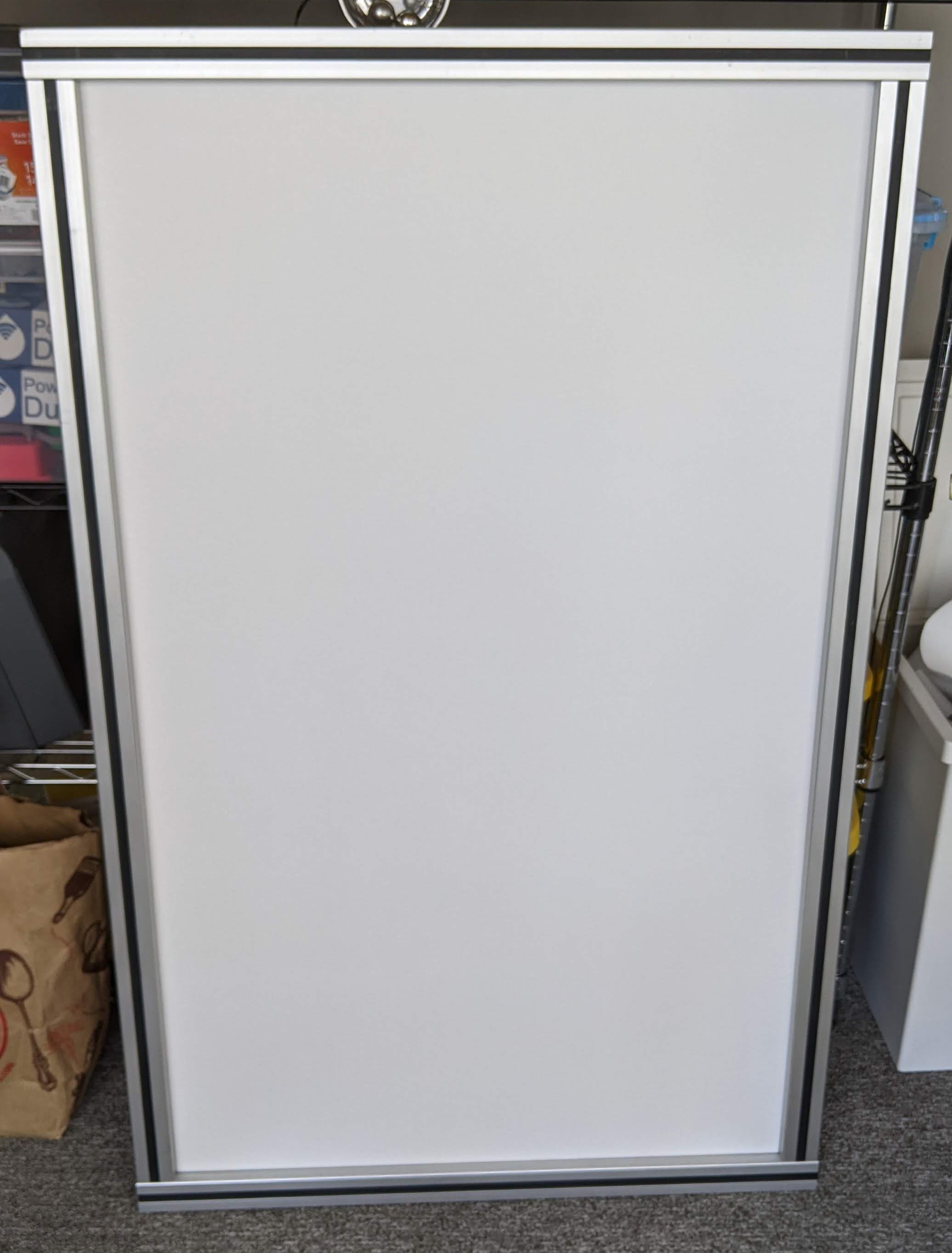
| Sandbox glass bottom sprayed with glue. The glass is the same size as the top cover and is 4.7 mm thick. |
 |
| Cloth backed white vinyl glued to the sandbox bottom glass. The excess material was trimmed from the edges with a sharp razor knife. |
 |
| This photo shows the two types of plastic inserts used in the sandbox bottom frame. The black one on the left side just covers the slot and sits flush with the surface of the aluminum. The one on the right side is for holding a plastic sheet, or in Arrakis 2.0, the glass sandbox bottom. When I bought the t-slot at a scrap yard I was careful to grab as many of the plastic strips as I could and they have proven very useful. |
 |
| Glass sandbox bottom installed in 45 mm t-slot frame. There are black plastic strips filling the slots in the frame. LED strip brackets will eventually be screwed to those plastic strips. This frame is larger than the XY frame by about 6 mm in width and length. |
 |
| View of the magnet carriage under the glass sandbox bottom. You can see the shadow of the ball. There's approximately 3mm air gap between the magnet and the glass. |
 |
| Sandbox frame sitting on top of XY stage frame. There are some 5 mm thick printed TPU spacers between the two frames. The sandbox frame is about 6 mm larger than the XY frame in X and Y dimensions. Wood side panels bolt to the sandbox frame using t-nuts and M6 screws. The LED strip brackets screw to the black plastic strips that fit in the slots in the frame. |
 |
| Bottom side of the LED strip frame showing 3D printed corner pieces. The frame is made of prefinished polystyrene foam, and the corner pieces are 3D printed PETG. All of it is solvent welded together using ethyl acetate (works for both PETG and polystyrene). |
 |
White LED strip frame positioned as it will be in the sandbox. The frame prevents direct view of the LEDs. It's made of dense polystyrene foam. I printed some corner pieces (under the frame) and solvent welded them together using ethyl acetate (sold as "MEK Substitute"). The frame is made about 2mm smaller than the inside of the sandbox to allow it to just drop into place.
|
 |
| The side panels are bolted to the sandbox t-slot frame. I haven't yet decided if these will be final and how they will be finished. As designed, the LED strip frame just drops into the box and sits on the LED strip brackets. It lifts out for easy redistribution or removal of the sand. |
 |
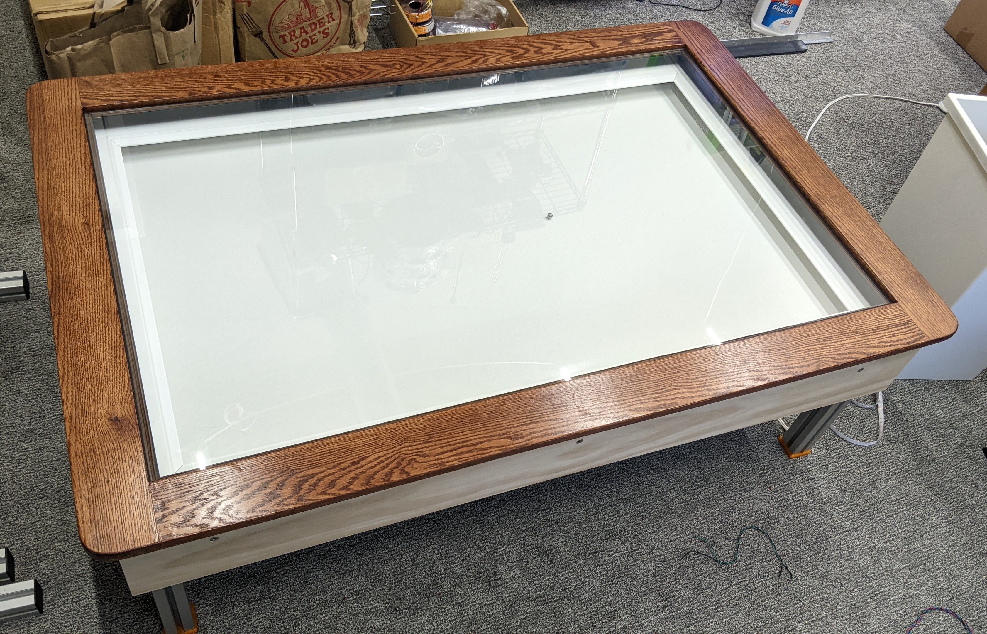
| Original oak wood framed glass top in place. It all fits nicely together, simply by stacking the different parts. The XY frame stands on the floor, the sandbox on top of that, the LED strip frame inside the sandbox, and the oak top cover frame on top of the sandbox and the top glass drops into the oak frame. |
 |
| One corner of the table showing the screws that hold the side panels on the sandbox t-slot frame. There's room for Ms.Kitty to go under the table now, so I'll be adding a cardboard cover to the bottom of the XY frame to keep her away from the belts. I have not sealed the sandbox with silicone and may not bother- it doesn't seem to "leak" much, if any, baking soda. |
Electronics updates
A while back I got a deal on a bunch of 5m long RGB LED strips with IR remote control, controllers, and power supplies. Each controller has sockets for two LED strips, and each socket has 4 wires- +12V, red, green, and blue LED grounds. I resoldered the wires in the controller for one of the LED strips so that they will light up in different colors. The remote control allows adjusting brightness and selecting some color cycling modes that I'll probably never use. There's no way (yet) to control the color from within the pattern files.
The original electronics used five power supplies- one for each motor and one for the controller board and two buck converters to power the LED strips. Arrakis 2.0 now uses a single, 24V, 350W power supply, one buck converter, and adds two ReDump protection circuits and an LED controller driving 12V RGB LED strips. I remounted the electronics and added hinges to the panel so it can be stored out of sight under the table when I'm not doing maintenance on it.
 |
| The LED controller wiring for single color operation and rewired for two color operation. If you select white, all the LEDs light up in both strips. Any other color selection yields two different colors. |
LED strip controller PCB before rewiring for two color operation. There are 2x 4-wire cables on the left. I rewired one of them, swapping the order of the wire connections, so that the LED strips would (almost) always light up in different colors.
 |
| Electronics mounted on hinged plate. The hinges allow the plate to be stored out of sight under the table and swung down for easy access if I need to service any of it. I haven't worked out how it will latch in the up position under the table yet. The buck converter and LED controller are stuck to the power supply using some industrial adhesive tape. |
 |
| Arrakis 2.0 wiring diagram |
 |
| Arrakis, the original. |
 |
Arrakis 2.0.
I haven't decided how to finish the side panels yet, and I'll have to reprint the feet in some less offensive color now that they are visible. Maybe I'll do something to make the legs look better, too. |
|
 |
| One of the new color combos made possible by the RGB LED strips. |
 |
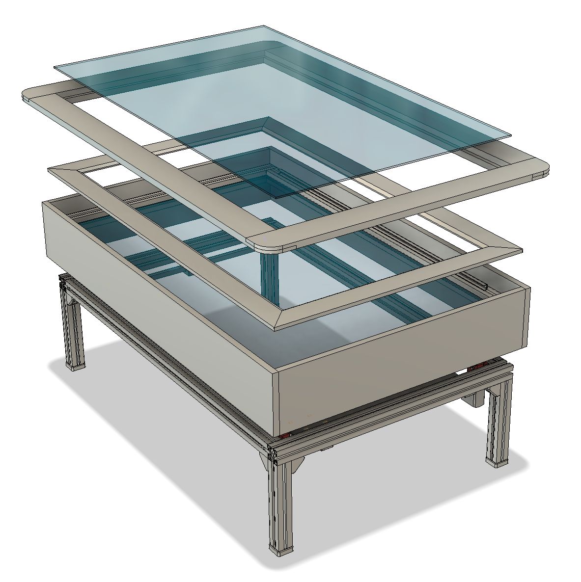
| This is how the five layers stack from bottom to top: coreXY mechanism, glass bottom sandbox, LED strip cover, oak wood top cover frame, top cover glass. |
The biggest problem with the table now is that Ms. Kitty thinks it's hers, and throws everything I leave on it to the floor. I guess she likes it to be clear so she can chase the ball without crashing into anything.
Bearing replacements
After I brought the table back home from the Maker Faire, it ran fine for a few hours then suddenly started making some terrible grinding noises when the Y axis moved. I surmised that the bearings were worn through and the mounting screws or metal pins were scraping on the aluminum t-slot.
I originally used PTFE for the sliding bearings in early iterations of The Spice Must Flow and Arrakis because I was pushing the stepper motors to their limits and wanted the lowest possible friction. The servomotors have much more "grunt" than the steppers did so I can afford a little more friction in trade for better wear resistance. I milled new bearings from some UHMW PE stock I found at the Makerspace and installed them in the Y axis bearing blocks and the magnet carriage. It runs quietly again, and hopefully the bearings will last longer than the PTFE did.
Cat Proofing
Now that there's no "skirt" around the table, I needed to protect the belts and wiring from Ms. Kitty, who likes to chew on things she shouldn't. I cut a large piece of corrugated board from a TV box to fit the bottom of the table and used packing tape to hold it on the frame. Then I added a couple screws and t-nuts with a piece of fishing line to hold the hinged electronics panel up so it would be mostly out of sight.
 |
| underside of the table with the corrugated board in place. |
 |
| View from the top side. If you look very closely you might see the fishing line that is holding the hinged electronics panel up. |
CAD File


