Arrakis 2.0 recently developed a minor problem- the ball started shifting while it was drawing patterns and it started making unusual noises. When I opened it up I found that the pulley on the left side motor had come loose, but wasn't completely rotating on the motor shaft. It would rotate a little with some reversals of direction, galling the motor shaft in the process.
I had used some locktite on the set screws for the pulley and couldn't get them to tighten, and could barely get them loose enough to get the pulley off the motor shaft. I installed a new pulley which quieted the mechanism back down and I decided to address a couple things I had been thinking about for a while.
The homing sensors were mounted high on the motor mounts and were easy to break if I was taking the table apart to transport it. I wanted to redesign that part of the mechanism so they sensors and flags could be positioned where they would be less likely to get broken.
There were three parts that needed redesign/print. The magnet carriage, the left side Y axis bearing/pulley block, and right motor mount.
Magnet carriage
The original magnet carriage design had a flag on the top piece which is why the X axis home position sensor was mounted in a precarious position on the right side motor mount. I wanted the sensor to be mounted lower, so I had to redesign the magnet carriage to put the flag on the bottom piece instead of the top piece. I also wanted to make the X home position somewhat adjustable and decided it would be easier to adjust the flag than to adjust the sensor position, so the flag is now a piece of plastic that attaches to the magnet carriage with a screw. The new magnet carriage consists of the old bottom piece that has become the top piece, and a newly designed and printed bottom piece that includes a tab to mount the homing flag.
Original magnet carriage. The projection to the left is the flag for the X axis homing sensor.
The new magnet carriage design. The old bottom piece has become the top piece and the flag (black) mounts with a screw so it can be repositioned if needed.
Right side motor mount
Now that the flag was moved lower, the sensor could be mounted lower, so the newly designed motor mount includes an extra wall to mount the X axis homing sensor. I mounted the sensor using some industrial double-sided tape. If the adhesive lets go, I'll drill some holes and screw the sensor to its mount.
The original right side motor and mount with the dangerously positioned X axis homing sensor.
The new right side motor mount with the X axis homing sensor moved to a much safer position.
Left side Y axis bearing/pulley block
The original design had the Y homing flag glued to the top of the pulley block and the sensor on the top of the left side motor mount, both in easily bumped positions. The new design has the flag printed as part of the bottom piece of the pulley block, and the sensor mounts on the side of the motor using the same tape I used for the X axis sensor.
The original left side Y axis bearing/pulley block with the Y axis homing flag glued to the top of the block.
The new left side Y axis bearing/pulley block with the homing flag printed as part of the bottom piece.
The original left side motor with the Y axis homing sensor mounted on top of the motor mount where it could be easily broken.
The new position for the Y axis homing sensor on the left side motor. It is taped to the motor using some double sided adhesive tape.
Now everything is secure and in positions that are not likely to get bumped when taking the table apart or putting it back together.
I liked Arrakis, but found some problems after living with it for a while.
The bottom of the sandbox was made of 1/4" Baltic birch plywood covered with a sheet of black EPDM rubber to keep the ball-rolling noise down. Most of the time it was fine, but with some patterns where the ball passes over the same area repeatedly, the sand would be pushed away revealing the black rubber. I didn't like that so much.
An even bigger problem was that the plywood warped depending on the weather, enough to close the air gap and the magnet would drag on the underside of the sandbox, making noise and producing wood dust. I put a lot of effort into making it run quietly, so this really bugged me.
Running the table at high speed causes the ball to throw the sand, so in the original design I separated the top and bottom as much as possible so I wouldn't have to keep cleaning sand off the underside of the glass top cover. It worked, but I decided that the bottom of the sandbox, where the drawings appear, was just too far below the top cover, requiring uncomfortable seating to view the drawings.
In packing up for the Maker Faire I found lots of PTFE dust in the mechanism- PTFE isn't ideal for sliding bearings for this reason.
In the interest of keeping this post relatively short, I won't go into too much detail, but will use lots of photos to show what changed.
Arrakis 2.0 Iced latte! See! I really use it as a coffee table.
Sandbox redesign and build
First, the legs were lengthened to raise the XY mechanism higher. Then I built a 45 mm t-slot frame to hold a sheet of 4.7 mm thick tempered glass (same size as the top cover!) and covered the glass with cloth-backed white vinyl. LED strips were mounted in aluminum C channel stock that was screwed to plastic strips that fit into the t-slots in the sandbox bottom frame. A decorative frame, made from prefinished white polystyrene molding, drops into the sandbox on top of the LED C channels. Side panels are made from 1x8" wood and simply bolted to the t-slot frame using t-nuts and countersunk M6 flat head screws.
Sandbox glass bottom sprayed with glue. The glass is the same size as the top cover and is 4.7 mm thick.
Cloth backed white vinyl glued to the sandbox bottom glass. The excess material was trimmed from the edges with a sharp razor knife.
This photo shows the two types of plastic inserts used in the sandbox bottom frame. The black one on the left side just covers the slot and sits flush with the surface of the aluminum. The one on the right side is for holding a plastic sheet, or in Arrakis 2.0, the glass sandbox bottom. When I bought the t-slot at a scrap yard I was careful to grab as many of the plastic strips as I could and they have proven very useful.
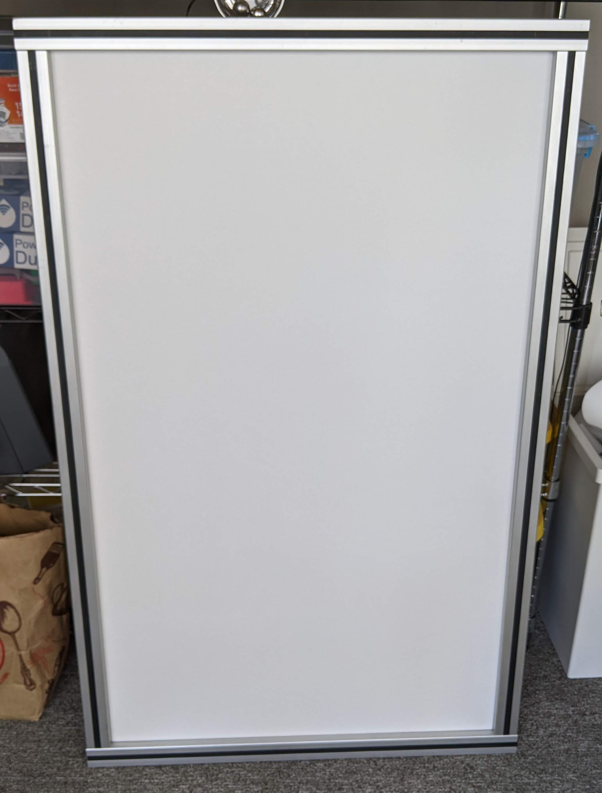
Glass sandbox bottom installed in 45 mm t-slot frame. There are black plastic strips filling the slots in the frame. LED strip brackets will eventually be screwed to those plastic strips. This frame is larger than the XY frame by about 6 mm in width and length.
View of the magnet carriage under the glass sandbox bottom. You can see the shadow of the ball. There's approximately 3mm air gap between the magnet and the glass.
Sandbox frame sitting on top of XY stage frame. There are some 5 mm thick printed TPU spacers between the two frames. The sandbox frame is about 6 mm larger than the XY frame in X and Y dimensions. Wood side panels bolt to the sandbox frame using t-nuts and M6 screws. The LED strip brackets screw to the black plastic strips that fit in the slots in the frame.
Bottom side of the LED strip frame showing 3D printed corner pieces. The frame is made of prefinished polystyrene foam, and the corner pieces are 3D printed PETG. All of it is solvent welded together using ethyl acetate (works for both PETG and polystyrene).
White LED strip frame positioned as it will be in the sandbox. The frame prevents direct view of the LEDs. It's made of dense polystyrene foam. I printed some corner pieces (under the frame) and solvent welded them together using ethyl acetate (sold as "MEK Substitute"). The frame is made about 2mm smaller than the inside of the sandbox to allow it to just drop into place.
The side panels are bolted to the sandbox t-slot frame. I haven't yet decided if these will be final and how they will be finished. As designed, the LED strip frame just drops into the box and sits on the LED strip brackets. It lifts out for easy redistribution or removal of the sand.
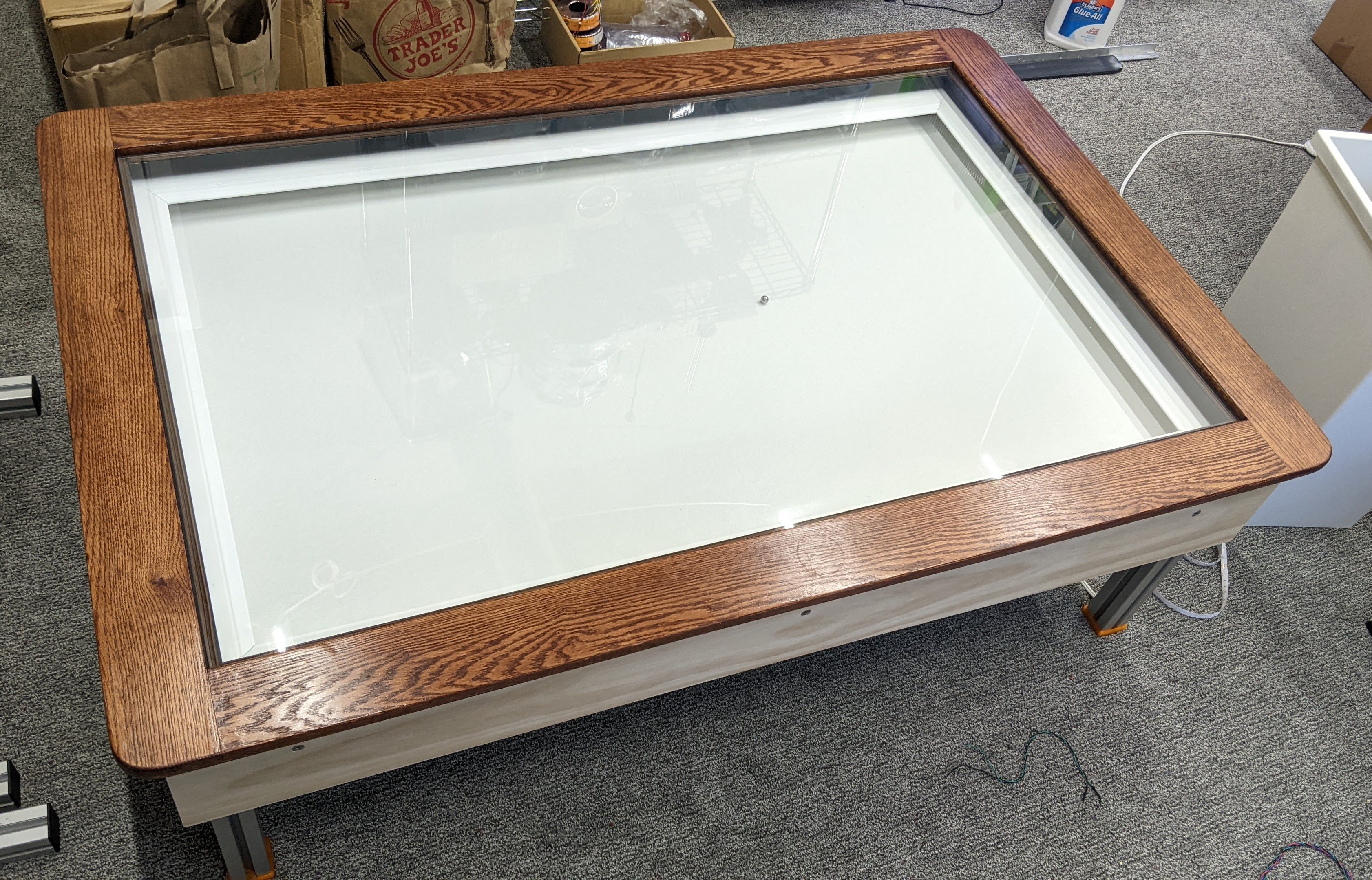
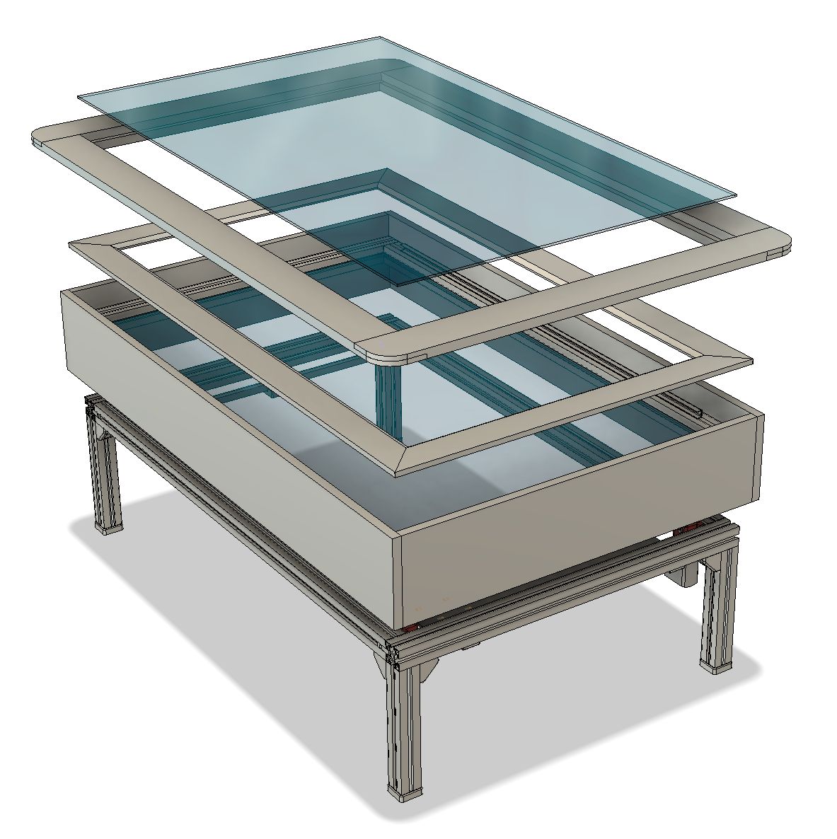
Original oak wood framed glass top in place. It all fits nicely together, simply by stacking the different parts. The XY frame stands on the floor, the sandbox on top of that, the LED strip frame inside the sandbox, and the oak top cover frame on top of the sandbox and the top glass drops into the oak frame.
One corner of the table showing the screws that hold the side panels on the sandbox t-slot frame. There's room for Ms.Kitty to go under the table now, so I'll be adding a cardboard cover to the bottom of the XY frame to keep her away from the belts. I have not sealed the sandbox with silicone and may not bother- it doesn't seem to "leak" much, if any, baking soda.
Electronics updates
A while back I got a deal on a bunch of 5m long RGB LED strips with IR remote control, controllers, and power supplies. Each controller has sockets for two LED strips, and each socket has 4 wires- +12V, red, green, and blue LED grounds. I resoldered the wires in the controller for one of the LED strips so that they will light up in different colors. The remote control allows adjusting brightness and selecting some color cycling modes that I'll probably never use. There's no way (yet) to control the color from within the pattern files.
The original electronics used five power supplies- one for each motor and one for the controller board and two buck converters to power the LED strips. Arrakis 2.0 now uses a single, 24V, 350W power supply, one buck converter, and adds two ReDump protection circuits and an LED controller driving 12V RGB LED strips. I remounted the electronics and added hinges to the panel so it can be stored out of sight under the table when I'm not doing maintenance on it.
The LED controller wiring for single color operation and rewired for two color operation. If you select white, all the LEDs light up in both strips. Any other color selection yields two different colors.
LED strip controller PCB before rewiring for two color operation. There are 2x 4-wire cables on the left. I rewired one of them, swapping the order of the wire connections, so that the LED strips would (almost) always light up in different colors.
Electronics mounted on hinged plate. The hinges allow the plate to be stored out of sight under the table and swung down for easy access if I need to service any of it. I haven't worked out how it will latch in the up position under the table yet. The buck converter and LED controller are stuck to the power supply using some industrial adhesive tape.
Arrakis 2.0 wiring diagram
Arrakis, the original.
Arrakis 2.0. I haven't decided how to finish the side panels yet, and I'll have to reprint the feet in some less offensive color now that they are visible. Maybe I'll do something to make the legs look better, too.
One of the new color combos made possible by the RGB LED strips.
This is how the five layers stack from bottom to top: coreXY mechanism, glass bottom sandbox, LED strip cover, oak wood top cover frame, top cover glass.
The biggest problem with the table now is that Ms. Kitty thinks it's hers, and throws everything I leave on it to the floor. I guess she likes it to be clear so she can chase the ball without crashing into anything.
Bearing replacements
After I brought the table back home from the Maker Faire, it ran fine for a few hours then suddenly started making some terrible grinding noises when the Y axis moved. I surmised that the bearings were worn through and the mounting screws or metal pins were scraping on the aluminum t-slot.
I originally used PTFE for the sliding bearings in early iterations of The Spice Must Flow and Arrakis because I was pushing the stepper motors to their limits and wanted the lowest possible friction. The servomotors have much more "grunt" than the steppers did so I can afford a little more friction in trade for better wear resistance. I milled new bearings from some UHMW PE stock I found at the Makerspace and installed them in the Y axis bearing blocks and the magnet carriage. It runs quietly again, and hopefully the bearings will last longer than the PTFE did.
Cat Proofing
Now that there's no "skirt" around the table, I needed to protect the belts and wiring from Ms. Kitty, who likes to chew on things she shouldn't. I cut a large piece of corrugated board from a TV box to fit the bottom of the table and used packing tape to hold it on the frame. Then I added a couple screws and t-nuts with a piece of fishing line to hold the hinged electronics panel up so it would be mostly out of sight.
underside of the table with the corrugated board in place.
View from the top side. If you look very closely you might see the fishing line that is holding the hinged electronics panel up.
The parts I ordered from Mouser finally arrived, after 6 months of delays in getting the connectors. Here's one of the boards, fully assembled, using the 1W wirewound resistors and including the connector:
If you decide to build some of these circuits, you can skip the connectors and just solder the power in and out wires to the board.
Now back to the original post...
Prologue:
I wrote most of this post a couple months ago but didn't publish it because I was waiting for the connectors I ordered from Mouser Electronics. When I first ordered them, one piece was out of stock and due to be back in stock in a couple weeks. In a couple weeks I got an email informing me that the back ordered parts wouldn't be in for another month. A month went by and I got notice that the backordered parts were in stock but one of the other pieces was now out of stock. They're telling me that the parts should be in stock at the end of May.
I decided to try using the servomotors in my corexy 3D printer, Ultra MegaMax Dominator and wanted to have protection for the controller board and all the other stuff that connects to the power supplies that power the XY motors, so I went ahead and wired in the protection circuits without the In/Out connectors.
Next time I order parts, I guess I'll have them ship as they arrive in stock instead of holding shipment until all parts are available.
Why Does My Bank Account Require Protection?
A while back, when I was working on the Arrakis sand table, I discovered that one really needs to take some special precautions when driving servomotors (or steppers) at high speed and acceleration. I had a Duet controller board, a couple buck converters to power LED strips, and servomotor, all connected to a single 200W 24V power supply. I made the mistake of driving the mechanism into the end of an axis at 1500 mm/sec. The sudden stop caused the motor's kinetic energy to be converted to electrical energy which ended up on the power supply line, blowing up the controller board, power supply, and buck converters, about $200 worth of electronics, hence the title of this post.
Motors generate voltage that opposes the voltage trying to make them turn. Under certain conditions, they can generate more voltage than the driving voltage. Those conditions include driving them at excessive speed, manually turning them (such as when sliding around the extruder in a 3D printer by hand), and slamming into physical stops while they are moving at high speed (like I did). In the Arrakis sand table, a simple error in generating the pattern file that's a little bigger than the actual table dimensions (combined with an incorrect axis maximum definition in the config file) can cause such a sudden stop. In servomotors like the iHSV series parts I used in Arrakis, the specified maximum rotational speed, 3,000 rpm, is limited by the self-generated voltage. When generating a pattern file for Arrakis, it's easy to make a mistake that will drive the motor beyond the 3,000 rpm limit.
Protection can take different forms. In Arrakis, which runs RepRap firmware on a Duet WiFi 3D printer controller board, I can program speed, acceleration, and travel limits in the Duet's configuration files. In theory, the fault condition should never occur. However, all that assumes that the controller hasn't lost its mind, that there are no mechanical failures, and that the dumbass (specifically, me) experimenting with the mechanism remembers to set the correct software limits in the controller.
What is really needed is a device that will protect my bank account from my stupidity, an insane controller board, or a mechanical failure in the mechanism. Preferably it will be a circuit that will sense a fault condition and keep it from damaging the electronics that might be sharing a power supply with the motor.
Someone on a web forum pointed out a protection circuit in an app note from Gecko Drives, a company that makes stepper and servo motor drivers.
The circuit is pretty simple- the 1,000uF cap absorbs small current spikes that may occur under normal operation of the motor. Normally, motor current from the power supply goes through the diode to the integrated motor/driver. In the event of a sudden motor stop due to hitting the limit of an axis, or a bearing seizing up, or some object blocking the motion, the motor will put a reverse current spike on its power line. That will cause the voltage on the capacitor to rise above the power supply voltage, reverse biasing the diode (switching it off) which will turn on the transistor, dumping the current coming from the motor to ground via the 33 Ohm resistor. The power supply and anything else connected to it will never see the voltage/current spike from the motor.
I ran a simple simulation in LTSpice to see how it works. The voltage source on the left is the 24V power supply and the current source on the right stands in for the motor.
It's not much of a model, but it roughly demonstrates what happens in the circuit:
The green trace is the current in the motor. It starts at -3.4A, which represents the loaded motor current supplied by the 24V power supply (V1). When the current reverses direction (the fault condition) the voltage across the motor(blue trace) rises. Current through R3 (33 Ohms) starts at about zero because the transistor is off. When the voltage across the motor rises above 24V, the transistor turns on and current through R3 (red trace) rises. The power supply voltage is the light blue trace- notice it barely moves.
I decided I needed to build some of these circuits as I have 4 more of the motors waiting for projects (in addition to the two that are in Arrakis). I thought about hay wiring them, but it didn't seem like a good idea, so I needed a printed circuit board. I asked around the makerspace and a couple people recommended KiCAD, so I gave it a try.
Parts Selection
When you lay out a PCB, you need to know exactly which parts you're going to use in order to select appropriate footprints. The app note doesn't say too much about the parts so I made some calculations of basic specs then went shopping. I decided to use through-hole mounting for all the parts because they're easy to handle and solder.
The motor current normally flows through the diode so it has to be rated to handle it. The data sheet on the motors seems to indicate that the nominal load current for the motor is 3.4A (3.4A x 24V=81.6W, and the motor is advertised as a 78W motor, so the current seems about right) and that the driver will alarm (and hopefully shut down?) at 300% of that. 300% of 3.4A is 10.2A, so I chose a 15A 100V Schottkey diode (SMC 15SQ100). In normal operation, with 3.4A going through the diode and voltage drop of 0.5V, the diode will have to dissipate about 1.7W, so it's going to get warm/hot (assuming the motor is loaded and drawing full current).
In the "Arrakis Incident" the motors were brought to an abrupt stop which is what caused the voltage/current spike that blew up the power supply and other electronics. If there had been a protection circuit like the one here, after the stop and current spike, the motor might have started up again (the power supply wouldn't have been dead) and run until it slammed into another hard stop. And it might have kept going, over and over. Hopefully, I'll be there watching it and will shut off power before the repeated slamming around does any damage.
The iHSV motor's integrated drivers appear to monitor the motor speed and/or supply voltage and will shut down the motor/driver if you try to drive it so fast that the self generated voltage exceeds the power supply voltage by some unknown amount. Other motor and driver combos may not do that.
If you try to drive a motor beyond it's spec rpm limit, the voltage at the motor will rise, Q1 will shut off, and the motor will slow down or stop until Q1 turns off again, and then the motor speeds up again repeating the cycle (again, the iHSV motors don't seem to do this). In some mechanisms it might keep doing that until someone notices that something is wrong and shuts down the machine. That means R1, R2, R3, and Q1 will all be working to dissipate energy from the motor on a repeated basis.
I point out the different types of faults because it affects the component selection. When Q1 is off, the normal state, R1 and R2 have very tiny current passing through them. In a fault condition, the current goes up and depends on the magnitude of the voltage/current spike produced by the motor. A 20V rise will cause 20 mA to go through R1 and R2. A 76V rise (which puts us up to 100V, the rating of capacitor C1) will drive 76 mA through them. 20 mA will dissipate 0.4W and 76 mA will dissipate 5.8W. Unfortunately, I can't really predict how the iHSV motors behave. There's no way to know what the voltage/current spike will look like under different fault conditions, and I'm not prepared to risk destroying a motor to find out. I chose to use 1W resistors for R1 and R2 and hope that will be sufficient. I used wire wound resistors because they can tolerate power surges better than other types. The ones I used are good for 10x their rated power (=10W) for 5 sec.
The app note specifies a TIP147 Darlington PNP transistor, so I chose one in a TO-220 package. Does it need a heatsink? This also depends on the magnitude and duration of the fault. I think it will only operate for a few seconds at a time under fault conditions, so I think it is safe to dispense with a heatsink.
This is a relatively high current circuit, so I chose a 4 pin Molex MegaFit connector rated for 23A per pin. I also ordered crimp terminals and shell for the plug that mates with J1.
I put together a BoM with part numbers from Mouser and Digikey here. You can make all sorts of substitutions and find the same or similar parts from other dealers. Prices in the BoM are approximate, of course.
Designing the PCB
I watched a few youtube tutorials on using KiCAD, and dove in. One thing I found out is that if you're going to have PCBs made by OshPark or other board maker, it's best to set up the board maker's design rules before starting the board layout.
I went to the OshPark website and looked up their design rules and checked them against the defaults in KiCAD. It turns out there were no issues so I didn't really have to change anything. A more complex board or using surface mount parts might require some of the changes.
Next I drew the schematic diagram:
Once the schematic was entered, I selected footprints for the parts. I checked data sheets for part dimensions and selected appropriate footprints from the KiCAD libraries. Then I just dragged the parts into position, paying attention to the net connections, defined the outline of the board, placed mounting holes, and started putting down traces. I used a filled area on the top of the board for a ground plane and put the rest of the wiring on the bottom of the board.
I had to change the connections to the connector a few times before arriving at the final pinout. Some pinouts led to difficult arrangement of the components on the PCB that required jumpers, etc. I found that by playing with the connector pinout I could create a very simple layout for the board.
The diode will carry the full motor current under normal operation, so the metal traces on the board need to be pretty wide to ensure low resistance and heating. There are a bunch of on-line PCB trace width calculators that will give a pretty good idea of the required trace width for any given current, trace length, and temperature rise. I used this one. I put the diode very close to the connector pins to minimize the high current trace lengths and used 10mm wide, filled areas for those connections for the same reason. They should be able to handle the fully loaded motor current and even the peak current without burning up, even with 1 oz copper.
The capacitor and transistor CE loop are the only other places that are likely to see much current so I used wider traces for those to minimize resistance/heating.
The final steps before ordering the board are to run a design rule check, fix any problems that it reveals, and then export Gerber and drill files.
This is the final layout which I have named REDump for "returned energy dump":
The board layout just before design rule check. The outline of the connector extended beyond the edge of the board so I had to edit it back to pass DRC.
The board is relatively large, 60 x 65 mm, due to the large sizes of the capacitor, 33 Ohm resistor and the connector. I used 4 mm mounting holes set at 50 and 55 mm spacing. I kept the edges of the board clear so that it could be mounted in slots in the walls of a case instead of using the screw holes.
I deliberately hung the connector beyond the edge of the board so that if I print a case for it the connector can protrude through the wall and the wall will mechanically support the connector. This overhang was flagged during the design rule check so I edited the footprint silkscreen layers so they wouldn't be drawn beyond the edge of the board.
I ordered a prototype run of 3 of the boards for about $30 from OshPark.
I probably should have used bigger holes, pads, and pad spacing for the diode and the 1K resistors. When I order more boards I will make the changes to the files.
Assembly
There are no tricks- just put the leads through the holes and solder them down. Pay attention to polarity of the diode and capacitor, and make sure you put the transistor in the right way- the heatsink tab should be toward the connector.
Note- the 1W resistors and connector are all still back-ordered after about 4 months, so I built it using 1/2 watt resistors and no connectors.
Testing
I did some static tests to verify operation- first just applying supply voltage to the input and making sure it appeared at the output with a resistor substituting for the motor. Then I applied a voltage to the output to make sure sure the diode turned off and the transistor turned on.
Finally, as I was preparing to install the servomotors in UMMD, I made a test video that indicates the protection circuit will indeed protect the power supply and other circuits from a voltage spike generated by the servomotor.
Installation
When you connect potentially high current wires it's best to avoid ground loops. That means each ground wire should go all the way back to the power supply. That's how I wired this into UMMD. The REDump board ground has a wire back to the power supply ground, and the ground from the motor goes back to the supply ground, not to the REDump board ground.
That means a 3 wire cable is required at the REDump connector. The crimp terminals listed in the BoM are for the plug that fits the jack on the PCB, and are for 14 or 16 gauge wire. If you're going to use some other gauge you'll need to order a different part number for the crimp terminals.
It's also a good idea to twist high current wire pairs, so when I installed the REDump boards in UMMD, I twisted the ground and supply leads from the REDump board back to the power supply, and twisted the motor ground lead around the supply wire from the REDump board together, then continued twisting the ground lead from the motor around the ground and supply leads from the REDump board back to the power supply.
In the future I'll be installing these boards in Arrakis so I can start experimenting with really high speed drawing without having to worry about what might happen if there's a mechanical failure.
TSMF had three main problems - it was too big to use at home, a little too noisy, and didn't look like furniture that would be acceptable in my living room. I decided to build a new, smaller table, with a more presentable finish, that I could use as a coffee table. It would have to be the right size, the right height, and as quiet as a mouse. I think I succeeded, though you may not care too much for the finish...
The result is "Arrakis", named for the sand covered planet in the Dune novels by Frank Herbert.
Arrakis, in all her glory! I gave her a haircut after this photo was taken, trimming off the fur peeking out from under the glass top inside the box.
Here's what I did that is different from TSMF.
The Mechanism
The Arrakis mechanism is smaller, and closer to the floor to make it more usable as a coffee table.
TSMF's mechanism had a couple problems. The 45 mm square t-slot frame was a little flexible. I found that the belt tension was sufficient to cause the Y axis frame rails to bow outward. When X direction motion reversed, especially near the center of the table, the entire X axis would shift in the Y rails and make a clunking noise. I made a partial fix by bracing the frame with crossbar made of wood that helped prevent the rails from bowing, but it was still a problem.
I wanted a definitive fix for that problem in Arrakis so I spring loaded one of the Y axis bearings so that the X axis couldn't move back and forth between the Y axis rails, even if they bowed outward. I had also had a failure of one of the Y axis blocks due to poor design (the X axis tube was tight fit to the blocks and tended to split the printed layers apart). The new block design was made in two pieces, with screws that clamped it together over the X axis guide tube.
Here's the bearing/pulley block that has the sprung bearing. The light orange part is a PTFE bearing that fits in the t-slot of the XY mechanism's frame. The block at the other end of the X axis is identical, except the PTFE bearing is screwed to the block instead of sliding on pins.
The right side Y axis bearing/pulley block that has the sprung bearing as seen in the video, above. The three screws hold the two printed pieces together, clamping the X axis guide tube (black). One screw passes through holes drilled in the X axis guide tube. The pulleys are made from stacked F625 bearings and held in place with 5mm steel pins (you can see one pin sticking up a bit at the top).
This is the left side Y axis pulley/bearing block. In this one, the PTFE bearing that fits into the t-slot is screwed to the block. There's a flag for the Y axis opto endstop glued to the top of the block.
Another view of the right side Y axis bearing/pulley block.
TSMF's magnet carriage was also a problem. The magnet fit into a square hole with a light spring that kept the magnet pressed against the bottom of the sandbox. Dragging the magnet against the wood was noisy (and created dust under the table). It got even noisier when the motion changed direction. The magnet would rattle in its hole in the carriage and against the bottom surface of the sandbox.
In Arrakis, I wanted the quietest possible operation, so I redesigned the magnet carriage. Now the magnet is glued to the carriage so it can't rattle, and it is separated from the bottom of the sandbox by an air gap.
The magnet carriage. The screws that hold it together also help anchor the belts. The belts are folded over the screws and clamped against themselves with teeth interlocked in narrow slots. You can just see the PTFE bearings contacting the X axis guide tube. There are four such bearings and their contact pressure on the guide tube is adjusted using shims made from soda cans.
The magnet is glued to the top of the carriage using silicone glue. The "blade" is the flag for the X axis optical endstop. In order to home the X axis, the Y axis must be homed first.
This video shows how the pieces of the magnet carriage go together. There are four screws that hold the printed pieces together at the corners and serve as part of the belt clamping system. The blue parts are PTFE blocks that act as bearings to allow the part to slide on the X axis guide tube. I used shims made from soda cans to adjust the pressure that the bearings apply to the X axis guide tube.
Here is a video of the mechanism running at 200 mm/sec with plenty of close-ups of all the parts:
The Electronics
When I switched from steppers to servomotors in TSMF, I used two power supplies- one 150W supply powered one motor and a 200W supply powered the other motor, the controller board, and the LEDs (the LEDs had two buck converters to step the 24V down to 12V).
The schematic is the same as TSMF, except that I added a separate power supply (not shown) for the Duet controller board:
As I was working on the Arrakis mechanism I learned something about servomotors the hard way. I had finished putting the mechanism together and wanted to test the motion so I loaded a TSMF pattern file and started it up. I didn't consider what might happen running a large pattern on a smaller table. The magnet took off and quickly slammed into the end of one of the axes, coming to a loud and abrupt halt. The machine stopped dead and wouldn't respond to commands.
I did some research and found that that is a well known/understood problem among people who use servomotors. The problem is the kinetic energy of the system gets turned into electrical energy when the mechanism is blocked. That causes a voltage spike on the power supply line which, in this case, killed a power supply and the Duet WiFi controller board. Shortly after this, the small buck converters that were powering the LEDs from the same power supply also failed. I was lucky that the voltage spike didn't also kill the integrated driver in the motor.
I replaced the power supply, Duet WiFi board, and the buck converters (this time using higher power units), and added a separate power supply for the Duet board.
I found a protection circuit that will prevent power line spikes coming from the motor from doing that sort of damage, and have all the parts in hand, but need to come up with a circuit board for it. Watch for a blog post on the circuit board. In the meantime, I have provided the controller board with its own power supply to keep it separate from the motor.
Protective circuit for servomotors. If the voltage at the motor gets higher than the voltage from the power supply, the transistor turns on and shunts the voltage to the 33 Ohm resistor. When the motor voltage drops back to the supply voltage the transistor shuts off and everything operates normally.
In TSMF the electronics were mounted in a box that was attached to one of the table's legs. In Arrakis I mounted all the electronics on an aluminum plate screwed to the mechanism's frame. I used a Duet WiFi controller board so I wouldn't have to have a control panel on the table. Power on/off is controlled with a foot switch on the line cord. I used a white line cord because the table is best viewed in the dark and I didn't want to be tripping on the cord in a dimly lit room.
Electronics mounted on aluminum panel that's bolted to the t-slot frame. Left to right, 150W 24V power supply, Duet expansion board, Duet WiFi controller board, 200W 24V power supply. The other side of the plate has a small 24V supply for the controller board and two buck converters to power the LED strips in the sand box.
CAD rendering for positioning electronics.
Expansion board (left) that provides step/dir/enable to servomotors, Duet WiFi controller board, and 200W 24V power supply.
The Sandbox
TSMF's sand box was made with 1 x 8" pine sides and a 1/2" plywood bottom. Pine isn't very good for much besides coffins, and is too soft- it will show every little bump. I wanted a different look for Arrakis so I ordered some red and blue fur that matches the LED lighting inside the table. I also wanted to use a thinner bottom panel so I could put an air gap between the magnet and the box to reduce noise.
I found that running TSMF at high speed would throw the sand with some of it sticking to the cover because the cover was too close to the sand. I had to open it up to clean the cover frequently. I designed Arrakis with the mechanism close to the floor and the glass cover about 230 mm above it, at coffee table height, to minimize cover cleaning.
As you may have seen in some of my photos and videos, I have a cat. She has one bad habit- she likes to chew on wires. I designed Arrakis so the sandbox would come down very close to the floor to keep Ms. Kitty away from wires and belts. If you build something like this you might also want to design it to keep pets or little kids away from wires, belts, pulleys, and motors.
The sides of the sandbox are made of 1/2" Baltic birch plywood. The corners are held together using aluminum corners of the type used to make musical instrument cases, and rivets. That's one decision I regret for reasons I'll explain below.
The bottom of the box is made of 1/4" Baltic birch plywood. That allowed me to put the air gap between the magnet and the bottom of the box which reduced noise. During construction and testing the mechanism with the unfinished sandbox in place I noticed that the steel ball rolling on the plywood bottom of the sandbox made quite a bit of noise. I wanted to try to reduce ALL noise, so I did some experiments and found that a rubber coated steel mouse ball was very quiet (unfortunately, large diameter). Then I tried a steel ball rolling on a rubber sheet- also very quiet.
I ended up gluing a sheet of black EPDM rubber roofing membrane to the bottom of the sandbox. That created another problem- it caused the plywood to warp. Eventually I got that under control and it went into the sandbox without any problems. The corners of the sandbox and the bottom edges are sealed with black silicone and the inside of the box is painted with matte black paint.
Gluing the rubber sheet to the plywood caused the wood to warp! The PVC pipe was used to roll out bubbles trapped under the rubber. I later added staples to the edges of the rubber sheet, in case the glue ever lets go. I was able to get the warp out by putting a couple pieces of wood under the ends of the board and standing on it a few times. It also seems to have settled a bit with time.
The outside of the sandbox was finished by gluing on pieces of high density 1/2" upholstery foam covered with blue and red striped fur cloth to match the LEDs that light up the table. The cloth was folded over/under the side walls and stapled to the plywood. The seams were hidden by cutting the cloth on the red/blue lines and carefully matching them up before stapling. As each piece was mounted, I glued the edges of the cloth to the foam, then carefully matched up the red-blue lines on the cloth so there would be no break in the pattern all the way around the table.
One corner of the sandbox showing the aluminum extrusion, rivets, printed spacers.
The sandbox was assembled on the granite counter top so the edges would all be in the same plane. The narrow strips are the supports for the plywood bottom of the box.
Installing the fur cloth. I painted the inside of the box black (well, more like charcoal grey), then cemented high density upholstery foam on the sides using a spray foam adhesive, then cut four pieces of the fur cloth (note the fuzz on the floor and in the sandbox), then stapled the cloth to the wood. You can see some printed neoprene spacers (red) that lift the box just enough to create the air gap between the magnet and the bottom of the box. The neoprene spacers were later replaced with printed TPU parts.
The box with the bottom in place and the cloth stapled down. LED strips are not yet mounted. I cut each piece of cloth along the red/blue lines and glued the edges to the foam so that there would be no visible seams where the different pieces of cloth meet. The fur hides the seams perfectly and I have a difficult time finding them even though I know they are there.
The top of the table is a piece of tempered glass that I bought for $6 via Craigslist. I made a frame for it out of oak by cutting the boards to length, milling in 1/2 lap joints at the corners, gluing them together, rounding the corners, sanding, staining, and finally finishing with oil based polyurethane. There is a black painted pine subframe that supports the glass. Eventually, I'll seal the glass to the top with silicone so that if some dope (probably me) spills a drink on the table it won't end up in the sandbox.
Staining the frame. The wood is 1"x4" oak cut to length and sanded smooth, with half-lap joints at the corners. The corners were rounded with a couple cuts with a pull saw and then sanded. After staining, I applied a few coats of oil based polyurethane, then added a sub frame to support the glass top.
The LEDs are the same strips used in TSMF, cut shorter. The printed plastic clips to hold the LED strips in contact with the aluminum L channel heatsink did not inspire confidence, so I drilled a bunch of holes at every third LED and used zip ties to hold the LED strips down. They are covered with some black painted polystyrene trim boards that hide the aluminum heatsinks and prevent direct view of the LEDs.
I discovered that the black paint didn't stick to the aluminum corners of the box very well and quickly chipped the paint when installing the LED strips. I touched up the paint afterward, but I expect it will probably start peeling soon. I may need to put some sort of primer on aluminum when it's time to fix the paint again.
cutting fur cloth with scissors- next time (?) cut from the back with a razor knife instead, and keep the vacuum cleaner close by.
aluminum corners for the sandbox, and the rivets used to hold them- paint doesn't stick well and the rivets take a lot of space. I think it would have been better to use 2x2 wood pieces and screws.
black EPDM rubber on the bottom of the sandbox- should have used white, and maybe faux leather instead of EPDM. Contact cement would have probably been better and caused less warping of the 1/4" plywood, too.
LED wiring- I need to put more effort into creating contacts on the sandbox and frame mechanism to connect LED strips just by dropping the sandbox into position on the frame. Maybe adapt some battery contacts...