One Level or Two?
The original design for corexy used belts that were on stacked on two levels. When you look at the photo below, one of the things that jumps out at you is that the belts appear to cross. They only do that because the designer chose to use separate axles for the corner pulleys. If the pulleys were stacked on common axles, the belts would not appear to cross.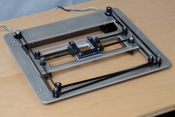 |
| Original corexy mechanism- belts are stacked- look closely at the positions of the pulleys on the motors. |
 |
| Close up of the Y axis pulleys set at different Z levels in order to maintain the parallel relationship of the belts and the guide rails. The corner and drive pulleys are set at two different Z levels, too. |
You can lay the belts out so they are on the same Z level. That requires separate axles and so lateral offsets for each and every pulley. It also requires that the belts cross over each other, usually at the M segment. The belts are going to touch there, so people usually put twists in the belts in that segment so that at the crossover point the smooth back sides of the belts are in contact instead of the toothed sides of the belts.
The thing that many people fail to notice, and that the original designer didn't explicitly state is that there are some critical relationships between the belts and the guide rails. The most important thing in any coreXY implementation is that the belt segments (a segment being the belt between two pulleys or between the extruder carriage and the end pulleys) whose length varies (labeled A-H in the diagram below), must be kept parallel to their respective guide rails. When I say parallel, I mean the literal definition of parallel in the XY, XZ, and YZ planes.
While you do need individual pulleys for each belt, they don't have to be laterally separated like the original mechanism. They can be stacked so that they share axles, as I did in building UMMD. That leads to a more compact layout (smaller footprint) that can be easier to build and align.
The motor placement relative to the Y axis guide rails determines whether you can share axles on the corner pulleys. If you put the motors outside the Y axis guide rails as in the diagram above, you can stack the corner pulleys on shared axles. If you put the motors inside the Y axis guide rails, the corner pulleys will have to be on separate axles- as was done in the original coreXY layout in the first photo, above. Your design goals and constraints may prevent you from placing the motors outside the Y axis rails. Either way works fine.
Keeping the belts parallel to their guide rails requires careful placement of the pulleys and motors. If you use laterally separated pulleys and axles, you will have 8 points (the locations of two of the corner pulleys, the four Y axis pulleys, and two motors) of potential error. If you stack the pulleys on shared axles, there are only 6 points of potential error to deal with.
In the explanations below, whenever I refer to belt segments with letters, this diagram is the reference:
 |
| UMMD's coreXY mechanism. All the pulleys are stacked, and belt segments A-H are parallel to the guide rails. |
As I have stated many times before, segments A-H must be parallel to the guide rails or the belt tension will vary with the position of the extruder carriage. It may not be obvious why, and I could spend hours deriving the trigonometric equations to calculate the lengths of the belt segments, but there's a much faster, easier way to get numerical values that demonstrates the importance of correct layout. I drew some sketches of the pulleys and one belt in a corexy mechanism, with belt segments B and G out of parallel with the Y axis. Here are the three sketches overlaid so you can see that the only thing that changes is the extruder carriage position and the lengths and angles of belt segments B and G:
 | |
|
 |
| Here are the dimensions of the parts. The layout is about what you might use for a printer that can print over a 200x200 mm bed area. |
 |
| Here's the area enclosed by the belts in the starting position. The important thing here is the value of the "loop length" - that is the perimeter of the area enclosed. |
 |
| Here is the area enclosed by the belt with the extruder carriage at the other Y position, 200 mm away from the first. The "loop length" is the perimeter of the area, essentially equal to the belt length (plus a little of the perimeter of the extruder carriage). |
Notice that the "loop length" -i.e. belt length - changes from 1368.3532 mm to 1358.4474 mm. That's about a -10 mm change in loop length over a 200 mm movement! That is why the belt tension will vary with the position of the extruder carriage if the belt segments are not parallel to the guide rails. The problem is the varying angle between the Y axis rails and belt segments B and G that depends on the extruder carriage position. If you had tensioned the belt with the extruder at the first position, it would tighten up when the extruder moved toward the second position. If you had tensioned the belt at the second position, the belt would get very loose as the extruder moved toward the first position. Belts are very strong, and they will not stretch 10 mm. That means something is going to fail. The mechanism is going to bind and stop moving, or maybe the motor is going to start spinning the pulley without moving the belt.
Maybe you're skeptical of the above. I have prepared a second set of sketches, similar to those above, but this time belt segments B and G remain parallel to the Y axis.
 |
| Here are three sketches overlaid, this time with the belt segments parallel to the guide rails. Once again, I moved the extruder carriage by 200 mm in Y, so the lengths of the belt segments change and the position of the Y axis pulleys and extruder changes. |
 |
| Here's the belt length (plus a little of the extruder carriage perimeter) with the extruder carriage in the first position. |
 |
| Here is the belt length (plus a little of the extruder carriage perimeter) with the extruder carriage 200 mm away from the first position. |
Notice that the loop length doesn't change even though the extruder carriage is moved by 200 mm. That means the belt tension will be constant regardless of the position of the extruder carriage. The only difference between this situation and the one above is that in this case, segments B and G are parallel to the Y axis guide rails. All these drawings are simplified- I did not include the thickness of the belt, as you should when you lay out and build a corexy design- more on that, below.
In the first set of sketches, I used a pretty extreme out-of-parallel layout (you can easily find examples of machines built that way all over the web), but the same principle applies even if the offset from parallel is much smaller or occurs in the XZ or YZ plane. In my illustrations, the X-parallel belt segments were actually parallel to the X axis guide rail. Now imagine what can happen if you combine out-of-parallel Y segments with out-of-parallel X segments...
 |
| Look at this layout for a corexy printer mechanism (from https://openbuilds.com/builds/printair-corexy.2718/) and see if you can spot any problems with the belt paths. It looks like none of the segments that are supposed to be parallel to the guide rails are actually parallel to the guide rails! How well do you think that's going to work? |
 |
| Here's a look down one of the Y axis rails in a printer called "autox3d". Do those short segments look parallel to the rail? |
 |
| Here's an image I used in a previous post... Absolutely everything about the belt routing is wrong in this build. Notice the belt wrapped around the drive pulley at the left-rear and notice the belt wrapped around the pulley at the right-rear. Do you think there is equal tension in those belts? Do you think the tension is going to be constant when the extruder carriage moves? Notice that the belts cross for some reason- vertically! Do you think this will print well? |
The examples above are just three of many you can find scattered around 3D printing web sites, so when you are shopping for a corexy layout to build, buy, or use as a base for your own design, study the designs carefully. Ignore claims that "it works OK" when the designer didn't understand and lay out the mechanism properly. OK to him may mean something different to you. OK for printing Yoda heads at the center of the bed may be different from OK to print threaded parts that screw together or parts that have to mate with other objects all over the bed plate. OK if it works for a couple weeks may not be OK if you want the machine to work for a couple years.
One thing you don't want to do is run a belt between two pulleys that are offset vertically (like the crossed belts in the picture above). GT2 and other gear belts have teeth that are perpendicular to the length of the belt. The pulleys have teeth that are parallel to the pulley's axis. The two are intended to be used with the belt running perpendicular to the axis of the pulleys and can't tolerate much offset. If you offset the pulleys and try to run a belt between them, the belt won't be perpendicular to the pulleys' axles. That will create a lot of stress/strain on the edges of the belt and wear on the pulleys and belt and will lead to premature failure. What this means is that if you build a machine with stacked belts, each belt has to stay on its own level, everywhere. Don't cross the belts at segment M and bring the upper belt down and the lower belt up. There is absolutely no good reason to do that and it will cause problems.
Belt Thickness
One of the fine points of laying out these mechanisms is including the thickness of the belt (or cable) in your layout planning. The belt thickness affects the locations of some of the pulleys and the attachment points at the extruder carriage, so it affects the design of the clamps at the extruder carriage.
GT2 belt, depending on who makes it and whether it's steel or glass core, comes in different thicknesses, usually 1.4-1.8 mm measured with a caliper. That difference matters because if you ignore it, the belts won't be parallel to the guide rails in the critical segments A-H.
Here's a typical drawing of a GT2 drive pulley, though many don't come with any drawing, and dimensions on drawings are often wrong:
 |
| The "outside diameter" value is what you would measure with a caliper on the pulley's teeth. The pitch diameter is used in selecting/sizing closed loop belts. |
Belts vary in thickness from one maker to the next, so you can't really use the pitch diameter value for laying out a printer mechanism. The best approach is to obtain the drive pulleys and belts you are going to use before you do the final layout so that you can measure the parts. Measure the pulley with the belt wrapped around it and use half that value (PBr in the photo below) when you plan the belt layout.
 |
| This is what happens when a belt wraps around a toothed pulley. If the belt thickness measured from the back to the tips of the teeth is 1.5 mm, when you wrap the belt around the pulley, the pulley's radius, Pr, increases to PBr which is less than Pr + the belt thickness. |
This is important because in a coreXY mechanism, the belt thickness affects how you position pulleys and belt clamps. For example, one side of the drive pulley belt goes to the Y axis bearing blocks, to smooth pulleys. If you just use Pr to figure out where to put the smooth pulley axle, the belt in segments A and G won't be parallel to the Y axis guide rails.
 |
| 20 tooth GT2 pulley diameter = 12.25mm, Pr= 6.125 |
 |
| The belt is 1.69 mm thick. |
 |
| Pulley plus belt diameter is 14.55mm, so PBr is 7.275 mm |
 |
| Laying out pulley locations. If you just use the measured diameters of the pulleys and ignore the thickness of the belt on the drive pulley (left), you will position the Y axis pulley in the wrong place and when you put a belt on it, the belt won't be parallel to the Y axis. You have to take into account the thickness of the belt on the drive pulley (right) to ensure that segment A will be parallel to the Y axis guide rail. |
If you're using the same size pulleys (bearings) at the corners, they should be positioned in line with the pulleys on the Y axis bearing blocks. You'll have to measure the diameter with the belt wrapped around them anywhere you use toothed pulleys and position them to keep segments B and H parallel to the Y axis rails.
Here's an easy way to think about it: the smooth back side of the belt has to be parallel to the guide rails. If you keep that idea in mind when you position the pulleys, you'll have no problems.
It seems like a small thing, but attention to detail like this is what separates great printers from not-so-great printers. I've shown what happens if the belt segments A-H aren't parallel to the guide rails- belt tension will vary with extruder carriage position. Changes in belt tension can allow the X axis to shift out of square with the Y axis (more on why, below) resulting in distortion in print geometry. The distortion may not be noticeable if you print at the center of the bed but will get worse as the prints move away from the center. Also, you set steps/mm in X and Y in the firmware configuration. That assumes that the belts are parallel to the X and Y axes of the printer and that the X and Y axes are square. If you change that relationship by improper positioning of the pulleys, steps/mm will vary with extruder carriage position, again resulting in distorted print geometry.
The same care is required when anchoring the belts at the extruder carriage. The belts/cables must be kept parallel to the X axis guide rail for all the reasons detailed above. In UMMD, I used 22 mm diameter F608 bearings for the Y axis pulleys. That meant I had to anchor the belts exactly 22 mm apart, and keep them parallel to the X axis linear guide.
One mystery surrounding steel reinforced belts is the minimum pulley size required to ensure long belt life. If the pulleys are too small, all the flexing around the pulleys will cause the steel reinforcement cables to fatigue and break, and then the belt will start stretching near the break in the cable. That causes all sorts of mysterious problems with the prints that are very hard to trace to the source.
Glass reinforced belts work well, even on smaller pulleys. Unless you're going to use very large diameter pulleys (maybe 30-50 mm), I'd stay away from steel reinforced belts for a coreXY mechanism. If you're worried about belts stretching, buy wider belts. 9mm wide glass core GT2 belts only cost a little more than 6 mm wide belts, and will stretch less for any specific tension. If you must use steel reinforced belts, be prepared to recognize the symptoms of failure and to replace them as they fail.
As you apply tension to one belt, you create a torque on the X axis. In the image below, the green arrows show the forces at P1 and P2 created by tension in the lower belt (also green). The blue arrows show forces at P1 and P2 due to tension in the upper belt (also blue). The orange arrows are the vector sum of the forces on P1 and P2 when the tensions on the belts are matched. If the tensions aren't matched, the orange arrows won't be pointing along the X axis and will cause the ends of the X axis to tilt relative to the Y axis as much as imperfections (slop in bearings, flex in the frame and guide rails, etc.) in the mechanism allow. The tensions in the two belts should be adjusted so that the X axis is square with the Y axis.
Here's an easy way to think about it: the smooth back side of the belt has to be parallel to the guide rails. If you keep that idea in mind when you position the pulleys, you'll have no problems.
It seems like a small thing, but attention to detail like this is what separates great printers from not-so-great printers. I've shown what happens if the belt segments A-H aren't parallel to the guide rails- belt tension will vary with extruder carriage position. Changes in belt tension can allow the X axis to shift out of square with the Y axis (more on why, below) resulting in distortion in print geometry. The distortion may not be noticeable if you print at the center of the bed but will get worse as the prints move away from the center. Also, you set steps/mm in X and Y in the firmware configuration. That assumes that the belts are parallel to the X and Y axes of the printer and that the X and Y axes are square. If you change that relationship by improper positioning of the pulleys, steps/mm will vary with extruder carriage position, again resulting in distorted print geometry.
The same care is required when anchoring the belts at the extruder carriage. The belts/cables must be kept parallel to the X axis guide rail for all the reasons detailed above. In UMMD, I used 22 mm diameter F608 bearings for the Y axis pulleys. That meant I had to anchor the belts exactly 22 mm apart, and keep them parallel to the X axis linear guide.
 |
| The belt clamps (yellow) were designed to match the diameter of the Y axis pulleys so the belts would be kept parallel to each other, and the clamps were carefully positioned on the extruder carriage to keep the belts parallel to the X axis. |
Steel Core or Glass Core?
The two most common GT2 belt cores are glass and steel. Both have several little "cables" inside that reinforce the belt to minimize stretch. Steel core belt reinforcement cables consist of a few stainless steel wires. Each glass core belt reinforcement cable consists of hundreds of micron-thin strands. Why pick one over the other?
 |
| Two different glass-core belts. I count 17 glass fiber cables in the top belt and 19 in the bottom belt. |
Though neither type will stretch very much, in theory, the steel reinforced belts will stretch less at any given tension. But there are other considerations.
Glass reinforced belts are much more flexible than steel reinforced belts. When you try to bend a steel reinforced belt around a pulley, it resists and tries to remain straight. In a coreXY mechanism, you have to bend each belt around at least five pulleys. That extra effort requires power from the motors. You have to pull harder on the belts to get adequate tension because the belt is resisting the bending more than a glass reinforced belt. That means your machine has to be built more solidly to use steel core belts.
One mystery surrounding steel reinforced belts is the minimum pulley size required to ensure long belt life. If the pulleys are too small, all the flexing around the pulleys will cause the steel reinforcement cables to fatigue and break, and then the belt will start stretching near the break in the cable. That causes all sorts of mysterious problems with the prints that are very hard to trace to the source.
 |
| The polyurethane belt can stretch where the steel cores are broken. This one came from the Z axis in UMMD which used a poorly designed belt clamp. |
In a coreXY printer, everyone wants to use small diameter pulleys to save weight and minimize size. If you want to use steel core belts, how small can the pulleys be? Since the manufacturers of the steel core GT2 belt usually don't provide that spec, we can look to the next best source of information, steel cable manufacturers.
Two of the determinants of minimum bend radius for a steel cable are the number of strands and the overall diameter of the cable. If you look at the tables, here, you'll see that as the number of individual strands of wire in the cable increase, the ratio of allowable pulley diameter to cable diameter decreases. The low end 3x7 cable has 21 strands and is OK to bend around a pulley that is 50x the diameter of the cable. At the high end, a 7x49 cable (343 wires) can be used with pulleys that are only 15x the diameter of the cable.
The glass reinforced belt cables are more like the high end of that table, with hundreds of strands of glass in each reinforcement cable, so they can be used with smaller diameter pulleys than the steel reinforced cable that is more like the low end of the table and requires 50x the diameter of the cable.
I took apart a steel reinforced belt to see what the structure of the reinforcement cables was like. I found, in the particular belt I looked at, 6 wires per reinforcement cable. That tells me that we need much more than 50x the diameter of the cable for the pulleys. It's hard to measure the "diameter" of the individual reinforcement cables because they are buried in the belt, but if we assume they are 0.5 mm diameter (the belt is about 1.7 mm thick, so a reasonable assumption), that would say that the pulley diameter should probably be more than 50 x 0.5mm = 25 mm. How much more is anyone's guess.
 |
| Here are the individual steel wires in a steel reinforced GT2 belt. In this particular belt, each reinforcement cable consists of 6 strands of steel wire. |
Tensioning the belts/cables
In the diagram showing corexy with stacked pulleys/belts, segments labeled A-H have to be parallel to the guide rails. As we've seen, that requires careful placement of the pulleys, motors, and belt attachments at the extruder carriage. The other belt segments J, K, and M, don't have to be parallel because their length is fixed by the placement of the motors and pulleys. That parallel requirement and the layout diagram can tell you the permissible ways to tighten the belts. You can do whatever you want to tension the belts as long as you don't disturb the belts' parallel relationships to the guide rails at segments A-H. That means there are several places where you can tension the belts. You can pull on the belts where they attach to the extruder carriage (pull only in the X direction), you can move the motors in the Y direction, or you can deflect the belts somewhere along segments J and K, or M. |
| Heavy black arrows indicate locations where you can adjust belt tension in the stacked belt layout. None of the adjustments forces any of the critical segments (A-H) out of parallel with the guide rails. You need to be able to adjust individual belt tensions so moving P3 and P4 in the Y direction isn't a good option. You only need one adjustment point per belt. |
 |
| Green arrows indicate the twisting torque on the X axis produced by the tension on the lower belt. Purple arrows represent the twisting torque on the X axis produced by the upper belt. If the torques are balanced, the net force will be inward as indicated byt he orange arrows. |
This is another reason why it is important to position the pulleys carefully, so that belt tension doesn't vary with the position of the extruder carriage. If the tension varies, there will be twisting torque applied to the X axis as the extruder carriage moves.
In corexy mechanisms, when you apply force to one belt (move one of the motors in the Y direction, for example) to change its tension, you also change the tension on the other belt. When you assemble the mechanism and adjust tension on the first belt, the X axis will shift out of square with the Y axis. When you adjust tension on the second belt, you do so until it pulls the X axis back into square with the Y axis. At that point if you feel the tension isn't high enough, you repeat the tightening sequence. See more about this phenomenon here:
https://drmrehorst.blogspot.com/2022/07/the-corexy-belt-tuning-myth.html
How much tension is enough? Unfortunately, that's hard to say. You can buy instruments that measure belt tension by pushing on a span of belt and measuring the deflection, but without any specs on the belts most people use, having a number isn't all that useful. Fortunately, belts work pretty well as long as you take out the slack. Some people pluck the belts like guitar strings to decide if they're tight enough and equal tension, but the real test of relative tension is the squareness of the X and Y axes, regardless of the absolute tension in the individual belts. So get them tight, but not too tight, and make sure the X and Y axes are square, and you should be fine. If the belts are too loose you might see some defects like ringing in the print surface that diminish if you tighten the belts. Ringing can be caused by acceleration and jerk settings, too, so adjusting belt tension alone isn't likely to cure a ringing problem.
All of the above also applies to machines with belts or cables that aren't stacked. While it is relatively easy to shift cables vertically, the segments A-H still must be kept parallel to the X and Y guide rails in all 3 planes. Cables are a whole different animal that have a unique set of problems and advantages. In a corexy mechanism, belts are a lot easier to deal with.
Update: I noticed some unexpected behavior in my sand table's corexy mechanism- the X axis was wobbling when the magnet carriage moved along the X axis. I did some tests on UMMD and found similar, but much smaller wobble and determined that the most likely cause of the wobble was imperfect drive pulleys. If the pulleys are drilled off center, belt tension will change as the mechanism moves which will result in the X axis wobbling. Fortunately it is a small problem and doesn't seem to affect print quality in any visible way. See: https://drmrehorst.blogspot.com/2020/12/x-axis-wobble-in-ummd.html

 The motors can be placed at any of the pulley locations, but it's best to have maximum belt wrap around the drive pulley. It's also better to keep the motors off the moving parts of the mechanism to keep its mass lower and to eliminate having to connect a cable to a moving motor, so the motors usually end up where I have been showing them in my diagrams.
Someone posted a question about belt tension (see below). He observed that the tension seemed to be higher in the shorter segments of belt than in the longer segments. When the mechanism is moving, the tension will vary a bit depending on the direction of motion and acceleration, but in a machine at rest, the tension in each belt should be the same everywhere.
We typically check the tension by pushing on the belt. When you do that you're lengthening the belt by stretching it (assuming the rest of the mechanism is rigid enough to resist the extra tension on the belt). What you're feeling with your finger pushing on the belt is the force required to make it stretch. If you push on one of the segments between the extruder carriage and the end pulley (segment E, for example) and one of the segments between the motor and corner pulley (segment J, for example), you'll find it is easier to deflect the belt in the longer segment, giving the false impression that the tension is higher in the short segment. The Pythagorean theorem easily explains why.
If you push on the center of a 100 mm segment and deflect it by 3 mm you're forming two right triangles with sides that are 50 mm and 3 mm long. The hypotenuse - i.e. the length of the belt - will then be sqrt(50^2 + 3^2) = sqrt(2509) = 50.09 mm. Your pushing on the belt has forced it to go from 100 mm long to 100.18 mm long, so you stretched it by 0.18 mm. If you do the same calculation on a 300 mm long segment, the sides of the triangles are 150 and 3 mm long. The hypotenuse of those triangles will be sqrt(150^2 to 3^2)= sqrt(2509)=150.03 mm. This time you have only stretched the belt by 0.06 mm for the same 3mm deflection. Of course it takes less force to deflect the belt- you're stretching it less.
If you have a Duet controller, it's possible to have the driver chips detect a stall condition on the motors and tell the firmware that the X and Y axes have reached the home position. I haven't tried to use that feature of the firmware yet to see if it is reliable and precise. I used old-school snap switches for the end stops because I know how to make them work reliably.
The Y axis endstop is sort of a no-brainer. You just mount your favorite flavor (snap, optical, or magnetic) switch on the printer's frame at one end of the Y axis and make sure that the Y axis will activate it. You don't need to attach any wires to any moving parts of the mechanism to do that.
The X axis switch is a different animal. If you want to be able to home the X axis regardless of the Y axis position, you'll have to mount the X axis endstop switch either on the Y axis where the extruder carriage can activate it, or on the extruder carriage where it will bump the end of the Y axis, and run a cable to the moving part of the machine. That means running wire to the switch in the extruder carriage cable or setting up a separate cable to the Y axis.
When I first set up UMMD, I mounted the switch on the extruder carriage. After thinking about it I decided that it wasn't necessary to be able to home the X axis regardless of Y axis position. I prefer to avoid running wires to moving machine parts whenever possible for reliability reasons, so I set up UMMD with the X axis endstop switch mounted on the printer's frame.
I mounted the X axis endstop switch on the printer's frame at the Y axis home position, then I set the firmware so that whenever the controller receives a command to home X or home all axes, it will always home the Y axis before it homes the X axis. In SmoothieWare you can just set the homing order of the axes to YXZ with this statement in the config file:
homing_order YXZ
In RepRap Firmware running on a Duet board you use the M98 command in the homex.g file to call the homey.g file first, then home the X axis. I also edited the homeall.g file to simply call homex.g (which will call homey.g, then home the X axis) then homez.g.
homex.g:
; homex.g
; called to home the X axis
;
M98 Phomey.g ; home Y axis first
G91 ; relative positioning
G1 Z5 F6000 S2 ; lift Z relative to current position
G1 S1 X307 F1800 ; move quickly to X axis endstop and stop there (first pass)
G1 X-5 F6000 ; go back a few mm
G1 S1 X307 F360 ; move slowly to X axis endstop once more (second pass)
G1 Z-5 F6000 S2 ; lower Z again
G90 ; absolute positioning
homey.g:
; homey.g
; called to home the Y axis
;
G91 ; relative positioning
G1 Z5 F6000 S2 ; lift Z relative to current position
G1 S1 Y310 F1800 ; move quickly to Y axis endstop and stop there (first pass)
G1 Y-5 F6000 ; go back a few mm
G1 S1 Y310 F360 ; move slowly to Y axis endstop once more (second pass)
G1 Z-5 F6000 S2 ; lower Z again
G90 ; absolute positioning
homeall.g:
; homeall.g
; called to home all axes
;
G91 ; relative positioning
G1 Z5 F6000 S2 ; lift Z relative to current position
M98 Phomex.g
M98 Phomez.g
I've been using it this way for a few months and it has worked fine. I have never needed to home the X axis independent of the Y axis position so it was a good change.
Update 12/1/20: I have replaced the microswitch endstops with opto interruptor type in all three axes. Do a search within this blog for the relevant posts. I changed to optical endstops because I like the fact that they light up when they are triggered, and I found that they are very precise.
People often forget about the size of the extruder and the impact that has on the size of the mechanism to move it and the size of the enclosure that will fit that mechanism. You have to design in some means of tensioning belts, and that type of stuff takes up space that has to be included in your design.
I suggest that if you're going to design and build a printer to have a specific print capacity, you start at the extruder carriage and work your way outward, with the frame/enclosure being the last thing you design. If the extruder is 100 mm wide, you're going to need a 400 mm wide space in order to move the nozzle 300 mm. If you think you might want to add a second extruder in the future, design the extruder carriage for it (or allow for the space it will take up) when you figure out how big to make your corexy mechanism.
In the diagram, above, that shows the possible belt tensioning locations, you'll notice that moving the motors and corner pulleys in the Y direction can be used to tighten the belts without disturbing the parallel relationships between the belts and the guide rails. People like to use t-slot aluminum extrusions to build printer frames. Combining the two ideas suggests that if you mount the motors and corner pulleys on the Y parallel frame members, you can apply tension to the belts simply by sliding the motors and/or the corner pulleys in the t-slot and locking them in place using t-nuts.
I recently designed and built such a mechanism using printed parts and cables instead of belts, but the concept will work with belts, too. In this project I didn't have many constraints except that the frame size had to be 1.9 m x 1 m, and I didn't try to maximize the area of movement. Whatever I ended up with would be big and big enough.
How much tension is enough? Unfortunately, that's hard to say. You can buy instruments that measure belt tension by pushing on a span of belt and measuring the deflection, but without any specs on the belts most people use, having a number isn't all that useful. Fortunately, belts work pretty well as long as you take out the slack. Some people pluck the belts like guitar strings to decide if they're tight enough and equal tension, but the real test of relative tension is the squareness of the X and Y axes, regardless of the absolute tension in the individual belts. So get them tight, but not too tight, and make sure the X and Y axes are square, and you should be fine. If the belts are too loose you might see some defects like ringing in the print surface that diminish if you tighten the belts. Ringing can be caused by acceleration and jerk settings, too, so adjusting belt tension alone isn't likely to cure a ringing problem.
All of the above also applies to machines with belts or cables that aren't stacked. While it is relatively easy to shift cables vertically, the segments A-H still must be kept parallel to the X and Y guide rails in all 3 planes. Cables are a whole different animal that have a unique set of problems and advantages. In a corexy mechanism, belts are a lot easier to deal with.
Update: I noticed some unexpected behavior in my sand table's corexy mechanism- the X axis was wobbling when the magnet carriage moved along the X axis. I did some tests on UMMD and found similar, but much smaller wobble and determined that the most likely cause of the wobble was imperfect drive pulleys. If the pulleys are drilled off center, belt tension will change as the mechanism moves which will result in the X axis wobbling. Fortunately it is a small problem and doesn't seem to affect print quality in any visible way. See: https://drmrehorst.blogspot.com/2020/12/x-axis-wobble-in-ummd.html
Myth Busting
I've recently seen on a couple different on-line forums posts by people stating that the two belts in a corexy mechanism have to be equal lengths. This is completely wrong. It happens that most people build machines symmetrically, so the belts will end up about the same length, but it is not necessary to build the mechanism that way.

Someone posted a question about belt tension (see below). He observed that the tension seemed to be higher in the shorter segments of belt than in the longer segments. When the mechanism is moving, the tension will vary a bit depending on the direction of motion and acceleration, but in a machine at rest, the tension in each belt should be the same everywhere.
We typically check the tension by pushing on the belt. When you do that you're lengthening the belt by stretching it (assuming the rest of the mechanism is rigid enough to resist the extra tension on the belt). What you're feeling with your finger pushing on the belt is the force required to make it stretch. If you push on one of the segments between the extruder carriage and the end pulley (segment E, for example) and one of the segments between the motor and corner pulley (segment J, for example), you'll find it is easier to deflect the belt in the longer segment, giving the false impression that the tension is higher in the short segment. The Pythagorean theorem easily explains why.
 |
| Deflecting a 100 mm belt segment 3 mm stretches the belt by 0.18 mm |
 |
| Deflecting a 300 mm belt segment by 3 mm stretches the belt 0.06 mm |
If you push on the center of a 100 mm segment and deflect it by 3 mm you're forming two right triangles with sides that are 50 mm and 3 mm long. The hypotenuse - i.e. the length of the belt - will then be sqrt(50^2 + 3^2) = sqrt(2509) = 50.09 mm. Your pushing on the belt has forced it to go from 100 mm long to 100.18 mm long, so you stretched it by 0.18 mm. If you do the same calculation on a 300 mm long segment, the sides of the triangles are 150 and 3 mm long. The hypotenuse of those triangles will be sqrt(150^2 to 3^2)= sqrt(2509)=150.03 mm. This time you have only stretched the belt by 0.06 mm for the same 3mm deflection. Of course it takes less force to deflect the belt- you're stretching it less.
Endstop Switches
Update: I replaced the snap switches with optical endstops in all axes in UMMD. I have also tested their precision and found them great! See these posts:
https://drmrehorst.blogspot.com/2020/01/ummd-gets-opto-endstops.html
https://drmrehorst.blogspot.com/2020/03/testing-ummds-xy-optical-endstops.html
Back to the original post...
The Y axis endstop is sort of a no-brainer. You just mount your favorite flavor (snap, optical, or magnetic) switch on the printer's frame at one end of the Y axis and make sure that the Y axis will activate it. You don't need to attach any wires to any moving parts of the mechanism to do that.
 |
| In UMMD the Y axis limit switch mounts on the P4 pulley assembly. A printed plastic bumper mounted on the end the X axis bumps the switch when the axis is himed. |
The X axis switch is a different animal. If you want to be able to home the X axis regardless of the Y axis position, you'll have to mount the X axis endstop switch either on the Y axis where the extruder carriage can activate it, or on the extruder carriage where it will bump the end of the Y axis, and run a cable to the moving part of the machine. That means running wire to the switch in the extruder carriage cable or setting up a separate cable to the Y axis.
 |
| The original extruder carriage in UMMD. The X axis endstop is near the top of the picture. The extruder carriage has changed a lot since this photo was made. |
When I first set up UMMD, I mounted the switch on the extruder carriage. After thinking about it I decided that it wasn't necessary to be able to home the X axis regardless of Y axis position. I prefer to avoid running wires to moving machine parts whenever possible for reliability reasons, so I set up UMMD with the X axis endstop switch mounted on the printer's frame.
I mounted the X axis endstop switch on the printer's frame at the Y axis home position, then I set the firmware so that whenever the controller receives a command to home X or home all axes, it will always home the Y axis before it homes the X axis. In SmoothieWare you can just set the homing order of the axes to YXZ with this statement in the config file:
homing_order YXZ
In RepRap Firmware running on a Duet board you use the M98 command in the homex.g file to call the homey.g file first, then home the X axis. I also edited the homeall.g file to simply call homex.g (which will call homey.g, then home the X axis) then homez.g.
homex.g:
; homex.g
; called to home the X axis
;
M98 Phomey.g ; home Y axis first
G91 ; relative positioning
G1 Z5 F6000 S2 ; lift Z relative to current position
G1 S1 X307 F1800 ; move quickly to X axis endstop and stop there (first pass)
G1 X-5 F6000 ; go back a few mm
G1 S1 X307 F360 ; move slowly to X axis endstop once more (second pass)
G1 Z-5 F6000 S2 ; lower Z again
G90 ; absolute positioning
homey.g:
; homey.g
; called to home the Y axis
;
G91 ; relative positioning
G1 Z5 F6000 S2 ; lift Z relative to current position
G1 S1 Y310 F1800 ; move quickly to Y axis endstop and stop there (first pass)
G1 Y-5 F6000 ; go back a few mm
G1 S1 Y310 F360 ; move slowly to Y axis endstop once more (second pass)
G1 Z-5 F6000 S2 ; lower Z again
G90 ; absolute positioning
homeall.g:
; homeall.g
; called to home all axes
;
G91 ; relative positioning
G1 Z5 F6000 S2 ; lift Z relative to current position
M98 Phomex.g
M98 Phomez.g
 |
| X axis endstop switch mounted on the printer's frame where the extruder carriage can activate it, but only if the Y axis is already in the home position. |
Update 12/1/20: I have replaced the microswitch endstops with opto interruptor type in all three axes. Do a search within this blog for the relevant posts. I changed to optical endstops because I like the fact that they light up when they are triggered, and I found that they are very precise.
Designing a CoreXY Printer/Machine
When you design any printer, you can work in different ways. You can start at the outside of the printer and design and build inward, or you can start on the inside and build outward. The former is better if you have very specific goals with regards to the overall size of the machine- maybe it has to fit in a specific cabinet or specific location in your house or office, and the latter is better if you have very specific goals for the printing capacity of the machine. If your goal is a specific print capacity, and you design and build the frame and enclosure first, you may have to struggle to fit the mechanism that meets your print capacity goal inside it and you might not be able to do it.People often forget about the size of the extruder and the impact that has on the size of the mechanism to move it and the size of the enclosure that will fit that mechanism. You have to design in some means of tensioning belts, and that type of stuff takes up space that has to be included in your design.
I suggest that if you're going to design and build a printer to have a specific print capacity, you start at the extruder carriage and work your way outward, with the frame/enclosure being the last thing you design. If the extruder is 100 mm wide, you're going to need a 400 mm wide space in order to move the nozzle 300 mm. If you think you might want to add a second extruder in the future, design the extruder carriage for it (or allow for the space it will take up) when you figure out how big to make your corexy mechanism.
In the diagram, above, that shows the possible belt tensioning locations, you'll notice that moving the motors and corner pulleys in the Y direction can be used to tighten the belts without disturbing the parallel relationships between the belts and the guide rails. People like to use t-slot aluminum extrusions to build printer frames. Combining the two ideas suggests that if you mount the motors and corner pulleys on the Y parallel frame members, you can apply tension to the belts simply by sliding the motors and/or the corner pulleys in the t-slot and locking them in place using t-nuts.
I recently designed and built such a mechanism using printed parts and cables instead of belts, but the concept will work with belts, too. In this project I didn't have many constraints except that the frame size had to be 1.9 m x 1 m, and I didn't try to maximize the area of movement. Whatever I ended up with would be big and big enough.
Motor mount rev 3 for cable driven corexy from Mark Rehorst on Vimeo.
 |
| The left corner pulley block, held in place with t-nuts. Cable tension is adjusted by moving the motor mounts (not the corner blocks) along the t-slot. If you try to adjust tension by moving the corner blocks, you pull both cables/belts tighter at the same time. You really want independent control of the tension on each cable/belt. |
 |
| The right side corner pulley block, a mirror image of the left side block. |
 | |
|
Notice the entire mechanism fits inside the frame, and the cables can be tightened by simply sliding the motor mounts along the slots in the frame. This particular project doesn't require micron accuracy or precision, so I wouldn't recommend duplicating it for a printer, but a similar mechanism could be built that will provide the necessary precision and accuracy, and very easy adjustment of belt tension, perhaps at the expense of the footprint of the machine being a little larger then it might be if it were optimized for small size.
After some testing of that mechanism, I decided that I didn't trust the noisy pulleys or my knot tying skills enough, so I redesigned the mechanism for belt drive. I put both belts on the same Z level, and twisted and crossed them at segment M. The corner pulley blocks then attached to both the X and Y parallel frame members so they can't be used to tighten the belts. Belt tensioning is done by moving the motors in the t-slot of the rail they are bolted to.
sand table mechanism converted to belt drive. from Mark Rehorst on Vimeo.
That same-level belt mechanism proved problematic, so I rebuilt it a third time using a stacked belt arrangement and it has been working fine ever since.


