Another recapping project: Luxman RX103 stereo receiver from 1982.
In 1982, no one at Luxman ever would have thought their product would still be operational after 42 years. This receiver has 157 electrolytic caps that will all eventually fail, though it only takes a couple to stop the receiver from working. The only way to continue using this receiver (which is working and sounding great!) is to replace all those electrolytic caps.
This job looks like a major project. There are a lot of caps and a lot of PCBs, and accessing them is going to require studying the thing and figuring out what needs to move to get to each of the 20+ circuit boards to be recapped. This reminds me of the first day of Calculus class I took in high school. You get the book and start flipping through it and your first thought is "I'll never figure all this out". But have patience, do a little at a time, and before you know it, you'll be through the whole thing.
I could disassemble the whole receiver right from the start and start recapping boards. However, there are too many screws, cables, and circuit boards to keep track of and I'd probably never get the thing back together again. My approach is to recap one board at a time, put it back including all the screws and cables that have to be removed to get at the board, and test it to make sure it's working. That way if it stops working I'll know where to look for the problem. It takes a lot more time to do it this way, but probably not as much time as it would take to troubleshoot after recapping everything and running into a problem, or maybe being unable to put it back together again.
When you do this sort of project, it's always best to have at least a schematic diagram that you can compare to the parts that are actually on the circuit boards. In this case, I actually had the service manual that someone was kind enough to copy and place on the internet for all to download. The manual includes parts lists broken out for each of the 20+ circuit boards in the receiver.
Luxman did several thing to make this job easier. First, the service manual contains lists of parts that actually include the capacitance and voltages instead of just cryptic Luxman part numbers. They also labeled all the components on the circuit boards and marked the polarities of all the caps. The manual has separate parts lists for each PCB, and caps on each PCB have numbers that are grouped for that board, making it easy to keep track of all 157 caps and where they go.
10/10/24: I'm writing this post and publishing as I progress, so on any given day, if you get to the bottom and the recapping isn't complete, come back in a day or two and check again. The power amp board will be one of the last because I ordered the wrong caps for it and I'm waiting for delivery of a new order.
VERY IMPORTANT NOTE: There is a button labeled "Remote Control" on the front panel of the receiver. If you push that button, you will not be able to hear any output from the amplifier. When you replace caps and start testing the receiver, if you don't hear anything coming from the amp, check that switch!
First step
Select and order replacement caps. I made a spreadsheet and copied the part numbers, cap values, and voltages of the original parts from the manual. Then I sorted it by part number, cap value, and cap voltage. That grouped all the same value caps next to each other. There were some caps with same value but different voltages. For those I looked for replacements at the highest (sometimes higher) rated voltages. For example, there were 47 uF caps at 16, 25, 35, and 50 volts used in the amp. I simply ordered some 35V and a few 50V caps for all of them. By doing that, the caps will last longer, and I will be ordering a larger quantity of the same part which drives down the cost, and I'll have fewer parts to sort through when I am replacing the caps.
I was able to find Nichicon caps for some of the parts, but not all, so the new parts list is a mix of Nichicon, Rubycon, Panasonic, and Kemet parts, all selected for low ESR and long life. A few low capacitance electrolytics are going to be replaced with film caps. Here is the spreadsheet of the parts I ordered. Total cost was about $70 from Mouser Electronics.
Note- I didn't receive the 22 uF caps I ordered, and I ordered the wrong physical size replacements for the 10,000 uF main filter caps. I also accidently order nonpolar caps for all the 0.47 uF 50V parts. I put together another order to replace all those, this time from Digikey. There's a separate page in the cap spreadsheet showing the parts I ordered from digikey.
Step 2: Power Supply (PS) Board Recap
I took the top and bottom covers off the receiver, set the screws aside in a tray, and looked at it for a while and saw that the PS board looked relatively easy to access and had lots of caps to replace, so that's where I started.
The PS board is accessed on the bottom of the receiver. In order to get it out to where you can turn it over for soldering, you have to clip a couple zip ties on a large cable bundle on the top side of the board, clip a few zip ties on the cables on the power supply board, and take out a bunch of screws- you have to remove the audio input connector screws on the back of the receiver, and the screws that hold down the PS board- see photos. You also have to remove the switch pushers that extend to buttons on the front panel.
Once you do that, you can wiggle the board out of the chassis and turn it over to access the solder side. Note: there are a lot of connectorized cables used throughout the receiver. The white ones will unplug, but the brown ones are soldered down and you can't unplug them.
 |
| Brown connectors used in some places in the receiver. These are soldered down, so leave them alone. |
 |
| Clip these zip ties on the top side of the receiver to loosen up the cable to the PS board so you can get the PS board out of the chassis. |
 |
| Power supply board on the bottom of the chassis, before recapping. |
 |
| The switch pushers are glued to the switches. Push them down to release them, then slide them to the left to remove them for PS board access. |
 |
| Remove screws at circled locations to release the PS board from the chassis. Once the screws are out you can wiggle the board out and flip it over (sorry, no photos of that). |
When I recapped the board, kept a copy of the spreadsheet with caps sorted by part number handy, and a copy of the PCB layout from the service manual. I removed one or two caps at a time, checking that the polarity marked on the cap matched the polarity marked on the PCB, and verifying the part numbers marked on the PCB. Once a cap was off the board I placed a check mark on the spreadsheet, checked the replacement value to insert in its place (voltages may be higher than the original parts), inserted the new part and soldered it and clipped the leads. Then I marked the layout diagram so I would know that that part was replaced. It's slow going, but helps ensure there are no errors.
 |
| Spreadsheet and board layout marked as each cap was replaced. 30 down, only 127 to go! |
 |
| Old caps from the power supply board. The brown stuff isn't leaked electrolyte, it's glue. |
 |
| Recapped power supply board back in place. Don't forget to put a drop of hot melt glue on the switch pushers after the whole receiver has been recapped (you will have to take them out again to access other PCBs, so don't glue them right after the PS board is recapped). |
After putting the PS board back where it belongs, I powered up the receiver and checked to make sure it was still working. Success! Now on to the next PCB...
Step 3: Remote Control (RC) PCB
The remote control PCB is located right next to the PS PCB, and is easy to access, so that one comes next. Now it could be argued that I'll probably never use the functions of the RC PCB, so I could just leave it alone, but if one of the caps on the board shorts out, it might take out a power supply that's needed for another part of the receiver, so replace the the caps!
 |
| The RC PCB circled in green. The only thing that holds it in place are the studs that mount the connectors on the back wall of the receiver. |
 |
| 4 little plastic studs hold the RC PCB into the receiver. Release them by pushing them out with a screw driver. |
 |
| After removing the studs, the RC board comes out easily. |
 |
| Underside of the RC board. No problem! |
There are just 6 caps on this board- all 1uF 50V parts. They are strangely labeled R080-R085 in the parts list, and some are labeled with R on the PCB, too. This is the only place these weird designations showed up in the service manual and on the PCB (as far as I know).
I replaced all 6 caps, put the board back into position, inserted the studs, and it was good to go. Only 121 caps left to go.
Next up: The "Decorder" Board (DB)
I think they meant "decoder", but I will continue to use "decorder" to refer to this board because that's what it's called in the service manual.
This one requires a bit of work to get loose. Start by clipping zip ties holding cables together over the board. Then disconnect the cables.
 |
| The "decorder" board sits right under the headphone socket. |
 |
| Zip ties cut and cable unplugged. |
 |
Remove the screws, and the headphone jack- see next photo.
|
 |
| Remove two bezel screws (one in the center of the pic, the other not shown farther to the left) and flex the bezel outward exposing the headphone socket clip (circled on the left). |
 |
| Slide the headphone socket clip out to release the headphone jack. Set it aside. |
 |
| You won't be able to get the decorder board out until you move the amplifier support rail out of the way a little. There are two screws at each end of the rail (circled, toward the right in this photo, only one end of the rail shown). remove the screws from both ends of the rail. The circled hole on the left is the bezel screw location that was removed to release the headphone socket. |
 |
| Remove these amplifier board screws from the support rail and the rail will come loose. You don't have to remove it, just loosen it so you can take out the decorder board. |
 |
| With the amplifier support rail loose, you can get the decorder board out of the chassis. |
 |
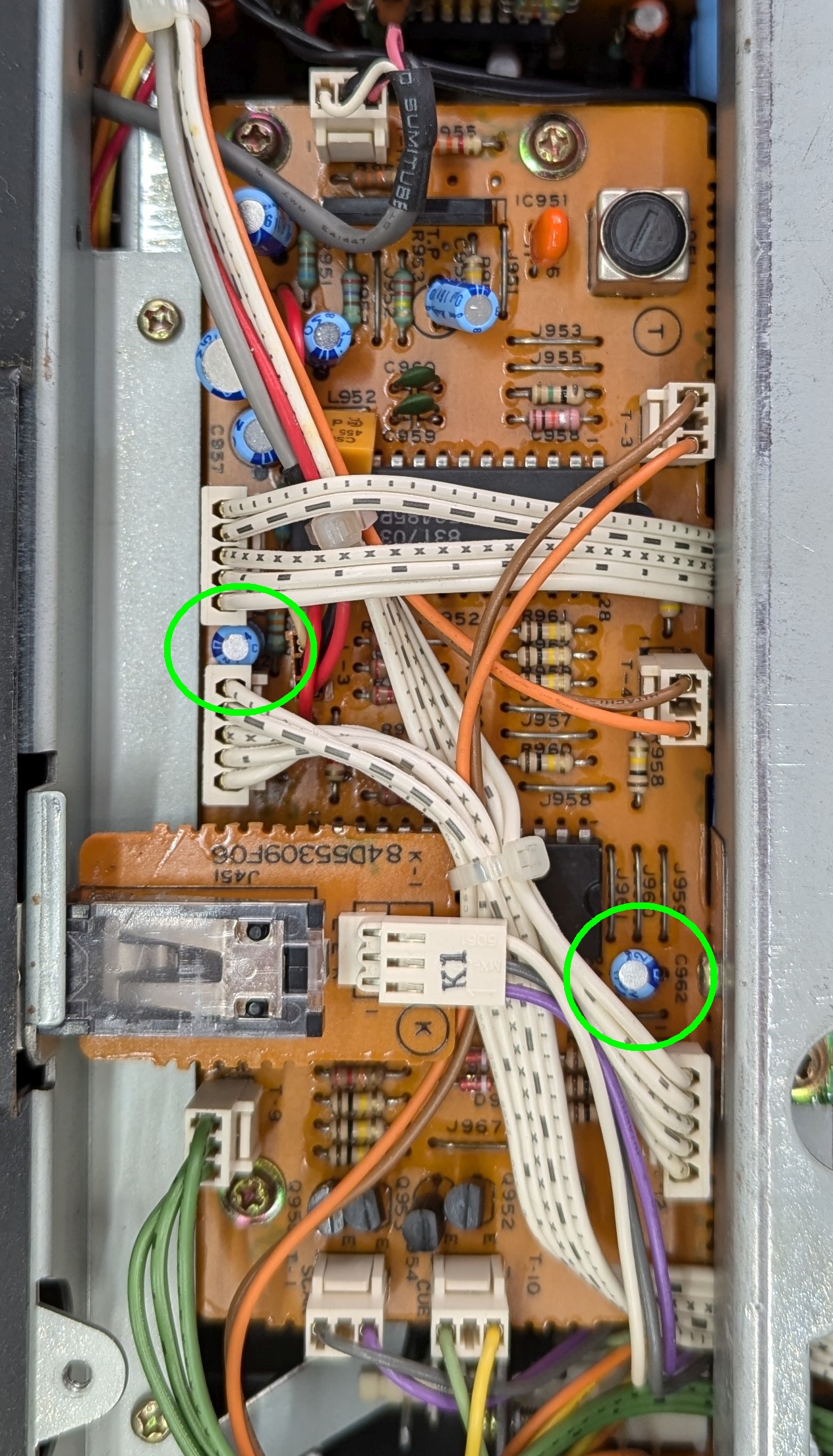
| Underside of the decorder board, ready for cap replacement. |
 |
| Uh oh! Both these caps labeled C962 on the PCB, and the service manual says C962 isn't supposed to be used, but C693 is, but is nowhere to be found. Hmmm. 2.2 uF 50V. I believe one of them is actually C963. I replaced both, hopefully I ordered extra caps and won't run out when I need that value on a different PCB. I have updated the spreadsheet to include C962. |
I removed and replaced the old electrolytic caps including C962 in two places (the manual says not to use). Hmmm. I think one of them is supposed to be C963. It was working with the caps on the board, so I replaced the caps. I may have to order more of that value if I run out when replacing caps on another PCB.
Reverse the process and put it all back together. Note- when you put the bezel screws back you have to make sure that all the radio station preset buttons are free to move. It takes a bit of wiggling to get them all into their holes in the bezel, so be careful.
Once it was back together, I hooked up speakers and tested it and it worked fine. 7 down, 116 left to go (with C962, the total number to replace went up to 158).
Next: the Tone Control Board (TCB)
Now we're going to flip the receiver over and work on the top side. The tone control board is low hanging fruit. All you have to do is remove two screws and the board comes out. You don't even have to remove the knobs.
 |
| The tone control board is mounted bottom side up. Remove the two circled screws to lift it out for cap replacement. |
 |
| Top side of the tone control board. Spray some cleaner in the pots while you have easy access. I removed the knobs, but it wasn't necessary to get the board out or back in. |
I ran into a small problem here. It seems the 22uF caps I ordered didn't arrive with the rest of the parts. I'll add them to an order with the others I missed.
 |
| TCB recapped, except for the two circled 22 uF caps. I'll have to come back to those after I get them ordered. |
Once again, I hooked up speakers, powered it up and tested it to find it working fine. 10 more down, 106 left to go.
Next up: Power Relay (PR) PCB
More low hanging fruit- the PR PCB has only one cap to replace. Take out 3 screws and carefully slide the board off the voltage regulator IC leads and it's ready to be recapped.
 |
| The board is mounted right next to the power transformer, accessible from the top side of the receiver. |
 |
| There are three screws holding the board down, circled in green. The cap that needs to be replaced is circled in blue. |
 |
| Screws removed, the board is loose. Carefully slide it off the 12V regulator chip (blue circle) leads so you don't bend them. |
 |
| Flip the board over and unsolder the old cap and solder in the new one. 2.2 uF 50V. |
Be careful when reassembling to slide the socket over the voltage regulator leads, then screw the board down. That one was easy! 1 more down, 105 left to go...
Next up: Full CAT PCB
More top-side low hanging fruit. The Full CAT board attaches to the chassis with just 3 screws which also help hold the receiver board down. Disconnect the cables, then remove the three screws and the board will be fully accessible.
 |
| The Full CAT PCB, mounted along side the radio PCB. Disconnect the cables then remove the screws that go through angle brackets that hold it down. |
 |
| Three screws hold the Full CAT board to the chassis. They're a little easier to access if you disconnect the cables first. |
 |
| Full CAT board with cables disconnected and screws removed. |
 |
Underside of the Full CAT board, ready for recapping.
|
 |
| Top side of Full CAT board, recapped. Instead of reinstalling it, might as well work on the radio board next... |
I ran into one problem on the Full CAT board. C305 was listed in the service manual as 4.7 uF @ 50V, but the part that was installed was 47 uF @ 16V. Hmmm. I installed a 47 uF @ 35V part.
That's 7 more down, only 98 left.
Next comes the Radio PCB
With the Full CAT board out, the radio PCB is half way out. There are a few more screws to remove, including the screws that hold the antenna terminal block against the back wall of the receiver, and one sneaky ground connection screw.
 |
| Screw locations to release the Radio PCB. The two at the top of the photo are accessed from the back of the receiver. The middle one on the right is a ground screw that is accessed from the right side of the receiver. |
 |
| Radio PCB ground screw. The board won't come out until you remove this screw and bend the ground strap down. |
 |
| Radio and Full CAT PCBs out. The radio board is ready for recapping. |
 |
| Bottom of the radio board, ready for recapping. |
I ran into several of the 22 uF caps that I didn't have, and realized that my 0.47 uF 50V electrolytics are all non-polar, and I don't want to install those where there was a polar cap, so I wasn't able to install all the caps in this board. I did install all that I could and will come back to it after I place another cap order.
There wasn't anything tricky about the recap and reassembly. Just get the radio board back into position, reconnect the ground terminal on the side of the chassis, plug the cables into the Full CAT board then screw both boards down. I hooked it up to speakers and an antenna and it's working fine.
28 more caps installed, leaving 70 more to go...
Next board: Speaker SW (SSW) PCB
This one is a little harder to get to and requires removal of the front bezel and power and speaker select buttons. It's also a good idea to remove all the selector buttons along the bottom front edge of the receiver. You can leave the radio station preset buttons alone.
Remove the bezel (3 pan head screws on top and 3 flat head screws on the bottom. Then loosen the screws on the both sides of the chassis so that you can slide the front panel assembly forward. Once it is forward you can remove the steel switch pushers from the SSW PCB. Disconnect T4 connector on the underside of the receiver on the decorder PCB. Finally remove three screws that hold the PCB into the chassis, loosen up the cables that connect to it, and work it out of the chassis.
This board has the speaker select switches, power switch, and speaker protection relay.
I wanted to do a little additional work on this board- the speaker A switch was intermittent and I wanted to fix that. I ran into similar intermittent switch when I recapped a Soundcraftsmen DX4000 preamp. The problem was that the solder joints had cracked. So when I had the SSW board out of the chassis, I resoldered all the switch/PCB joints. It worked. Both speaker switches are now reliable. Maybe I should go through all the other boards and resolder all the switch joints....
There are only 3 caps to change. C351, 352, and 353. Swap them out and put the pushers back on the switches, then put a drop or two of hot melt glue on each to ensure they don't come off the switches. Then carefully work the board back into position with the switch pushers protruding through the front panel. Push the front panel back and tighten the screws that hold it. Then install the three screws that hold the SSW PCB, and put the button caps back on the pushers.
 |
| Speaker switch (SSW) PCB viewed from the top of the chassis. |
 |
| SSW PCB from a better angle. You can see two of the three caps that should be replaced. |
 |
| Switch pusher- one of three. They are glued to the switches, but come loose easily if you pull them upward, close to the switches. |
 |
| Front bezel removed, the speaker switch and power buttons can be removed. |
 |
| Front panel screws released so the front of the chassis will slide forward. Also T3 pulled from the Decorder PCB on the underside of the chassis. |
 |
| These 3 screws will release the SSW PCB from the chassis. |
 |
| SSW PCB loose, pushers and buttons on the table. I got a little out of order with the photos, sorry. You should be able to wiggle the board out and flip it over to access the solder side and replace the caps. |
 |
Hot melt glue on the switch pushers before reinstalling the PCB in the chassis. Don't forget to plug in T3 and push the front part of the chassis back into position- you'll have to wiggle the switch pushers a bit to get them to fit into the slots in the front of the chassis. Once you get it slid back, tighten the screws that hold it there.
|
That's 3 more caps replaced, 67 to go.
Update 10/12/24
The new cap order has arrived, so I went back through the boards I already had out and replaced the 22 uF caps, and some of the 0.47uF caps with the new ones. That was 5 or 6 caps on two or three PCBs.
While I was doing that I ran into a couple 0.22 uF caps on the radio board that were listed as 0.47 uF on the parts list. Hmmm. I'll take a look at the schematic and see how they are used. I'll either order some 0.22 uF caps or install 0.47uF like the parts list says.
I also checked the new main filter caps for fit - perfect! I unsoldered the old ones from the power amp board without having to remove it from the chassis, then just soldered the new parts in. The pinout matches the old caps, and the new ones are 8 mm shorter than the originals. I ordered 12000 uF 80V caps ($14.10 each) vs the originals that were 10000 uF at 75V. The new parts are rated for 3000 hours at 85C, so should last many years at their normal operating temperature (life doubles for every 10C below rated temperature, so the new 85C parts should last 96000 hours at 35C).
 |
| Old and new caps. Identical pinout and spacing, easy replacement even without removing the amp board. |
After replacing those caps I tested the receiver again. I momentarily panicked when I couldn't get any sound out of it. But I checked the front panel switches and realized I had inadvertently pushed the "remote control" button. That killed the output, so I pushed that button again, shutting off remote control mode, and the receiver sprang back to life.
Next: Power amp (PA) board
Removing the PA board from the bottom side of the receiver is relatively easy- remove the switch pushers, take out all the visible screws holding down the output transistors, driver transistors, temperature sensors, etc., from the heatsink, and then a few more screws holding the PCB down on the heatsink and support rail toward the back of the chassis.
 |
| Removing these screws lets the PA board move enough that you can replace the electrolytic caps. While you're in there, clean the old silicone grease off the transistors and thermal washers so you can replace it with some fresh stuff. |
 |
| The PA board can tilt up when all the screws are removed from the transistors and the ones holding the PCB down on the heatsink and the support rail. It's a little too hard to access the caps that need to be replaced without freeing the PCB like this. Those are the new main filter caps already installed. |
When I was unscrewing the transistors from the heatsink, one of the driver transistor screws refused to unscrew and snapped off. I tried grabbing the end of it with vice grips and it still refused to come out. Hmmm.
 |
| This is the screw that decided not to come out. Notice how long the transistor leads are- I can drill a new mounting hole closer to the PCB to remount that transistor. |
I went through the board and replaced all the electrolytics, then used paper towels soaked in IPA to remove the silicone grease from the heatsink, transistors, and thermal washers.
 |
| One of the screws holding the driver transistors down on the heatsink decided not to come out. I grabbed the nub with a vice grips and couldn't get it to move. The solution is to drill another hole, closer to the PCB, and tap it, moving the transistor closer to the PCB. |
Now what? Looking at the way the transistors are mounted provided the simple answer. The transistors are mounted far from the PCB meaning their leads are quite long. All I have to do is to move that transistor closer to the PCB, drill a new hole in the heatsink and tap it so I can screw it back down.
The drill and tap will arrive tomorrow...
If that fails, I can always make a metal clamp that screws down at the adjacent transistor and will hold the problem part against the heatsink.
Still another disaster averted! The output transistors have a large metal pad on the back of the package to improve thermal transfer between the die and the heatsink. That metal pad is connected to the collector of the transistor so it has to be electrically insulated from the grounded heatsink. Thin mica washers are used to insulate electrically, with some silicone grease to improve thermal transfer while still providing electrical isolation. I was putting things back together and applied some "arctic silver" heatsink compound to the output transistors and mica washers. As I tightened down the screws, excess material was squeezed out. It occurred to me that Arctic Silver heatsink compound is probably just silicone grease loaded with powdered silver, which means it is probably electrically conductive. If the excess that was squeezed out connected the back side contact to the screws, it could short the transistors to the heatsink. I checked the output transistor lead resistance to ground (i.e. the heatsink) and found that the collectors of both 2SA1215 transistors were shorted to ground! I checked the schematic and no, the collectors of those transistors are not supposed to be grounded. BADBADNOTGOOD! I cleaned off all the Arctic Silver from all four of the output transistors, the heatsink, and the screws. What a mess! I'll be using this silicone pad material to replace the mica washers- no grease needed.
update 10/15/24
The silicone thermal gasket material arrived, along with a tool to punch neat holes in it. I marked it up for cutting and punching and got it done. I reinstalled the board, including the driver transistor that I had to move, checked to make sure there were no shorts between the output transistors and ground, powered it up- no smoke, sounded great!
 |
| Silicone gasket material and spinning punch used to make new gaskets for the output transistors. |
 |
| Power transistors reinstalled with new silicone gaskets. Driver transistor reinstalled in new location because its screw broke off in the heatsink. Rectangle at the bottom shows some minor damage to the PCB occurred when I removed the old main filter caps. These boards are brittle! |
That's a total of 14 more caps replaced, leaving 53 (I think) more to go...
Next up: a nightmare!
The rest of the boards that need recapping are all located in the front of the chassis. 7 or 8 of them are all in a sub chassis that is screwed to the main chassis. Getting those board out requires removing dozens of cables, and it's getting too complicated for me to document it because I'm having to try different things to get at the sub chassis, some of which work and others don't.
The front of the chassis can be folded down to get access to the back of the subchassis where most of the cables connect. You have to loosen the screws on the sides, then pull the front forward and tilt it down. The cables are working against doing that. So I think the best approach is take a bunch of photos, then clip zip ties holing the cables together, then tilt the chassis down and disconnect the cables. Then unscrew the sub chassis and take it out of the main chassis, then start attacking the individual PCBs in the sub chassis.
The Speaker Switch board has to come out again to get the sub chassis out.
There are screws on the sides of the subchassis that have to be removed to get some of the boards out and I don't think you can get at them without removing the subchassis, so out it goes!
 |
| RX103 receiver chassis with the subchassis removed. I clipped a lot of zip ties to loosen up the cables and make tilting the front of the chassis down easy. The subchassis comes out from the back side of the front of the chassis, and has to go back in that way, too. |
 |
| This is the bottom/front of the subchassis. There are 8 PCBs attached/packed into this little assembly. Some of the PCB slide out toward the front, some slide out toward the back, and a few are screwed down. |
 |
| This is the back of the subchassis. You can see many of the connectors and some of the labels on the plugs. There were a total of about 50 capacitors that had to be replaced scattered among these PCBs. |
Getting it back together shouldn't be impossible- each connector is marked with a unique identifier and the matching connectors on the PCBs are also marked. I marked a few of the connectors on the back side and marked the PCB where they plug in. The real trick will be not missing any of the cable connections, and getting the cables back into place and zip tied when it's all recapped.
Forget about recapping one PCB and then testing at this point. It will be far too much effort to put it all back together. I'll just do the recapping, reassemble, hope for a miracle, then test.
Wish me luck!
Update 10/17/24
I have finished replacing every electrolytic cap in the receiver! Now I have to put it back together so I can test it.
Update 10/18/24
I spent a few hours putting the subchassis back into the front of the receiver and reconnecting all the cables. There was one cable with the label smudged beyond reading, and a couple that had duplicate labels that required tracing the wires through the schematic diagram to figure out where they go. Once I got them all reconnected, and triple checked to make sure I wasn't missing any, I crossed my fingers, plugged in the receiver, and hit the power button. The standby light flashed for about 5 seconds, then the speaker relay clicked and out came very nice sounding music from the FM tuner. All the front panel lights worked and all the buttons worked. The vacuum fluorescent displays worked fine, too. Tone, volume, balance, and loudness controls all worked fine.
I put all the button caps except the preset memory buttons back, reinstalled the three long switch pushers, remounted the front panel, put in the preset memory button caps, and put in a couple zip ties on some of the cables- not nearly as many as there were originally, but I still have to fix the suckface when the belts I ordered arrive, and I'll need to tilt the front part of the chassis out of the way to get at the mechanism. That will be easier with the cables hanging loose. Finally I put the bottom and top covers back on the chassis and powered it up and let it run for a few hours to see if anything would quit working. No problems!
I marked the bottom cover with a permanent marker to indicate that all electrolytic caps were replaced in October of 2024.
Woohoo!
Looking back on the whole process, here's what I recommend to anyone thinking of recapping one of these Luxman receivers. From the start, remove the top and bottom covers, front panel and buttons, all knobs and extenders except for the volume control knob (the extender for that one is screwed to the potentiometer shaft), and the three long switch pushers. Clip most of the zip ties off the cables- it will be a lot easier to move the PCBs around. Be sure to have new thermal washers ready in advance for the output transistors. Have fun!
Update 11/01/24
I took apart the suckface mechanism to see about replacing the belt and getting it working again. I got it all apart and discovered that the belts I had ordered were much too thick to fit. I put it all back together again and decided I'm done. I can live without the suckface.
.jpg)


Were you able to get the phonostage to work with the suckface mechanism not working? I currently have a RX103 however the phonostage does not turn on.
ReplyDeleteYes, I got it working, but I don't have a TT to use with it. It was hard to trace the circuits because the manual I have is a poor pdf repro and it's hard to tell where wires connect and where they don't on the schematic. I don't think the suckface mechanism has anything to do with the phono stage.
Delete