Here are some of the techniques I have used to design assemblies of 3D printed part and non printed parts.
The first thing I do when designing 3D prints to fit with non printed parts is make CAD models of the nonprinted parts with enough detail to cover mounting the part to the print or other non printed parts. I have built up a library of nonprinted parts such as stepper motors, bearings, linear guides, etc. that I can reuse as needed, and Fusion360 allows direct import of 3D models of hardware from the McMaster-Carr catalog which can make life really easy.
Once I have modeled the non printed parts, I put the CAD models into their final positions relative to each other, then design the printed parts around them.
Get yourself a good caliper. It is the handiest tool there is for modeling existing objects. You can get cheap one on sale for about $10 at Harbor Freight Tools, but if you spend about $40 you can get one that doesn't have to be zeroed before every measurement, won't lose the battery cover, and will work for over a year on a single battery.
Copying/Modeling Existing Objects
In the printed blower photo below, I made an impeller (green) that was based on the design of an impeller from a CPAP blower. It looks pretty complicated by it's actually pretty easy to make such a thing.
First I took a picture of the CPAP impeller and measured its diameter and vertical dimensions.
 |
| | Here's the CPAP blower impeller, photographed from above. The goal is to copy the complex curves of the vanes on the rotor. |
|
Start by drawing the base disc that the vanes will grow out of and import the photo of the impeller being copied. Align the photo with the disc.
 |
| Model the base disc, and import the photo of the impeller and align it with the disc. |
Then use spline curves to trace the outline of one of the vanes:
 |
Impeller blade outline traced using a spline curve then pulled up in Z.
|
Create a sketch in the XZ plane to taper the vane to match the original
 |
| Sketch that will be used to taper the vane toward the edge of the impeller. |
Revolve the sketch and use it as a cutting tool to taper the vane.
 |
| The vane is tapered by revolving the sketch. |
Separate the vane from the disc by cutting the part with the top plane of the disc.
 |
| The vane is separated from the disc by cutting the vane component with the top plane of the disc. |
Copy the vane using a circular pattern.
 |
| The vane is replicated by creating a circular pattern. |
Finally, add mounting holes to match the motor and fillet edges, etc., and combine all the pieces into a single component. Export the STL file and you're good to go.
>>> sorry, Blogger deleted the image that is supposed to be here and I can't get it to reinsert it.
The same technique can be used to copy all sorts of things.
I used a similar technique to copy a finial from an antique table that a friend was refinishing.
In that project, I traced the outline of 1/2 of the profile of the object then revolved it into a solid.
If you buy parts from China, you'll often find that if there is a drawing showing dimensions on the web page where you order the parts but it may or may not match the parts they actually ship to you. I normally try to buy or scrounge gears, pulleys, belts, motors, switches, bearings, etc., first, and then design around them. I have learned the hard way to wait until I have the parts in hand so I can measure them and make sure things will fit.
Belts
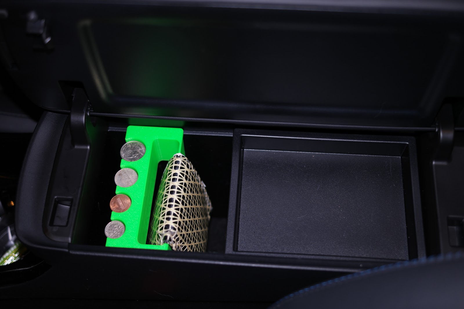
In machines that use belts, you have to clamp the belts to the moving parts. I like to use self locking belt clamps in which the belt folds back on itself with the teeth engaged. The problem is that every manufacturer's belts are different thickness, so you have to customize the clamp slots to match the belt. I printed this gauge to test the belts. It has a series of slots that are 1.0 mm to 3.0 mm wide in 0.1 mm steps. I use it to check the width for a single pass of the belt, and then fold the belt and see which slot will hold it with the teeth engaged.
 |
| GT2 belt gauge for designing self locking belt clamps. |
 |
| Self locking belt clamp. The entry and exit slot widths are determined using the belt gauge and the belt. |
Bearings
 |
| Hole gauge used to check fit with hard disk drive bearings. So far this gauge was used for a filament spool holder and Van de Graaff generator that used HDD bearings for the rollers. |
 |
| Cutaway view of the top of the Van de Graaff generator. The green parts are HDD bearings that let the roller (blue) spin very smoothly. |
 |
| Filament spool holder that uses HDD bearings (12 of them!) for the rollers and pivots. |
 |
| Rectangular gauge used to fit the Y axis bearing blocks on the ends of a "square" aluminum tube used for the X axis in the sand table project. |
Bosses and Alignment
Bosses and mating holes can be used to ensure accurate alignment of printed parts.
 |
Worm gear project that illustrates the wrong way to use bosses. The bosses and mating holes ensure accurate alignment of the two halves of the shell, but in this design, the screws go through the bosses the wrong way. The problem is that the boss is relatively small and weak. When the screw starts turning threads into it, the boss is liable to break off.
|
 |
| Test print made to check spacing between the shafts. 1/2" drill bits were used for the gear shafts. |
 |
| Bosses (done correctly this time) used to align the two halves of the box. The large screw hole goes in the boss, and the smaller hole that the screw will thread, goes in the boss's mating hole. |
 |
| Cutaway view of a boss with the screw in place. I usually make the boss 1 or 2 layer thicknesses shorter than the mating hole. The screw hole in the boss (the blue part) is larger than the screw diameter, so the screw just drops in. It will thread into the smaller hole in the mating part (orange). |
Here's a project I did a few years ago- it involved bearings, gears, a motor and three printed parts that all fit together:
 |
| Snakebite extruder printed parts and bearings. The base fits on a NEMA-17 motor. |
 |
| Bearings in place... rectangular bosses align the two top cover pieces to each other and the bearings. |
 |
Top cover halves in position... Bosses in the top cover align it with the base.
|
|
 |
| Gears installed... |
 |
| Final assembly. |
The other way to ensure alignment is to use steel pins and tightly fitting holes. You can buy 3-5 mm diameter stainless steel rods cheaply and cut them to the lengths needed, and have plenty left over for other projects.
Motor Mounts
One thing I see a lot of is motor mounts that look like L brackets, printed in plastic. That may work OK if the L is made of steel or thick aluminum, but plastic is a lot more flexible than steel and aluminum. Under belt tension or forces applied by gears, motor mounts like that will flex and that will cause belts to ride hard on pulley flanges, or gears to track poorly.
When I'm designing a motor mount, I start with a solid block and carve away just enough of it to allow belts, pulleys, and gears to be installed, then add whatever I need to mount it on the machine. You end up with a much more solid structure with minimal flex that way.
 |
| Looking at these two mounts, which do you think will flex more if it's printed? |
 |
| Here's a printed motor mount from the sand table project. |
 |
Here's one half of a motor and gearbox assembly I designed and printed. It was very solid.
|
|
 |
| Motor and printed gearbox. No thin, flexible parts allowed! |
In many situations, the best motor mount will not be printed, it will be made of metal. In UMMD, my coreXY printer, I made motor mounts from square aluminum tubing which is far more rigid than using a L bracket. You can drill mounting holes on the end opposite the motor, or on two sides, making placement very easy. Aluminum tubing is available in many sizes to work for different motors, and is pretty easy to work with. The hardest thing to do is cut the large hole for the motor's pilot (that's the name of the cylindrical bump on the shaft end of the motor). In NEMA_23 motors it has to be at least 38.1 mm diameter. There are a lot of ways to cut that type of hole- a hole saw on a drill press, or a milling machine with a boring bar, etc. Aluminum is easy to cut with a hack saw and drills easily, too.
 |
| Aluminum motor mounts I made for UMMD's XY stage. I cut the large holes using a boring bar on a milling machine, but there are ways to do it with less sophisticated tools. |
 |
| Here's one of those mounts installed in UMMD. |
One advantage of using aluminum tubing to make motor mounts is that it's thermally conductive and will act as a heatsink to help the motor run cooler.
Strength
I frequently use modifier meshes in Slic3r to increase fill density around screw and bolt holes. Meshes can be created in Slic3r, but I prefer to make them in CAD and export them as a separate STL file(s) that import into Slic3r.
If the modifier mesh touches the surface of the part, it will be visible in your print. You can make it invisible by putting it entirely within the print surface. If I am going to reinforce a vertical hole, I will put the bottom of the mesh about 0.4 mm above the bed plate and make it about 0.4 mm shorter than the print.
 |
| Thumbwheel with internal modifier mesh (green) in CAD (Fusion360). Note that the modifier mesh is 0.4 mm below the top surface and 0.4 mm above the bed plate. |
 |
| First bring in the thumb wheel... |
 |
| Then import the modifier mesh... |
 |
Then set the fill density of the modifier to 100%...
|
|
|
 | | Then check the preview to see that the modifier is there and looking as it is supposed to- the pink solid infill surrounding the hole. |
|
Using a solid modifier around the screw hole lets me crank the nut down on the thumb wheel screw without worrying about breaking the printed wheel.
Some people like to use threaded brass inserts especially for parts that will be screwed and unscrewed frequently. Keep in mind that the inserts are larger and their threads will never strip out, but they are still installed in printed plastic. If you apply too much force to the screw, you'll break the insert free of the plastic. We have a Taz printer at the makerspace that uses threaded brass inserts to hold screws that lock the Y axis guide rails to their mounts. Turning the screws too tight has jacked the brass inserts right out of the guide rail mounts.
I often use thread rolling screws for plastic. They look a lot like wood screws without the sharp point and have widely spaced threads that don't strip out the holes very easily. You can use wood screws and sheet metal screws too, as long as their sharp points are inside the print.
Holes
Holes always print a little smaller than the design size, so it can be useful to print a gauge of different sized holes to allow testing for fit. If you need really accurate holes, it is best to print slightly undersized pilot holes and then run a drill bit through them.
Hole templates like this one can be a quick reference to check printed holes against other hardware like bearings, screws, and bolts.
 |
| A printed hole template like this can be used to check printed hole size against design size. Numbers indicate design size, not actual hole size. The printed hole size will be a little smaller. than the design size. Make sure your extruder is calibrated before you bother printing something like this. |
If you're going to be mounting a bearing or other round object in a printed hole and you want it located accurately, when you slice you should use "random" seam placement so that the layer start/stop zits get scattered around the hole instead of all lining up to form a seam that will displace the bearing a little.
Thumb-wheels
Thumb-wheels have all sorts of uses including leveling and zeroing beds, hold down clamps, etc. There are different ways to make them, but I have found a pretty easy way that makes reliable thumb-wheels every time.
The trickiest part about thumb-wheels is preventing the screw from turning inside the printed plastic wheel. You can't do it with a round screw head. You need to either use a hex head bolt (great for larger stuff, but not so good for small screws) or put flats on the head of the screw using a grinding wheel or belt sander.
I use a lot of 6-32 screws because I have a bunch of them and they are a reasonable size for most things I need to adjust with thumb-wheels. You can't usually find them with hexagonal heads, so I grind flats on the sides of the heads. When grinding, you need to hold the screw tightly without damaging the threads and without burning your fingers as it heats up. I drill a hole into a wood block and drive the screw part way in. Then I put one side of the block on the belt sander table and start grinding until the the flat on the head meets the screw threads. Then I turn the block over and grind the other side of the screw head. The flats come out parallel and I don't burn my fingers.
 |
| 6-32 screw head ground flat. Careful positioning of the screw in a wood block allows you to preserve most of the tool socket. |
 |
| All the hardware you need to make a reliable thumbscrew. You can leave out the lock washer if you use a nylock nut or a drop of Loc-tite. |
 |
| Use a center hole that just fits the screw, and put in a depression for the flattened screw head. Flutes are made by drawing a circle at the edge of the wheel, using it to cut away the side of the wheel, then using a circular pattern to duplicate the cut around the wheel. |
The 32 TPI thread is about 794 um pitch which is very close to 800 um. Using 16 flutes means that each flute represents about 50 um of vertical displacement when you turn the screw.
Clearance between moving parts
One of the harder things to do is design moving parts for mechanical clearance. You can use a sketch and a rectangular or circular pattern to check simple clearance issues:
 |
| A sketch (blue) was done on an offset plane and uses a circular pattern to check for movement and clearance at the optical limit switch on the right side of the model. |
You can use "joints" in Fusion360 to show part motion in 3 dimensions. Place the joints and then grab one of them and move it with your mouse- the model will move just like the actual object will when it is assembled.
 |
| Rotary joints (the flags) were added at the bearings |
 |
| Select one of the rotary joints as a handle. |
 |
| Move the joint and the assembly moves. |
 |
| You can use this type of thing to model moving assemblies and check for interferences. |
Infill Patterns
Slicers have different infill patterns available. Some of the patterns consist of straight lines that run back and forth across the interior of the print (rectilinear, grid, triangles, stars, etc.), others are interesting looking 3D structures (honeycomb, 3D honeycomb, gyroid, etc.). Here's something to think about: patterns that print as a series of straight lines will print faster than patterns that use short lines and curves going in different directions.
All the motion in the printer is subject to acceleration and deceleration (and jerk or junction deviation). If an infill pattern consists of a series of short, straight lines going in different directions, such as the hexagon infill pattern, it will print slowly because the extruder carriage never gets to the target speed because it is limited by the acceleration. The printer is going to shake a lot while printing that type of infill, too, because the direction of motion changes every few mm.
 |
| Short segments and many rapid direction changes means hexagonal infill will print slowly and shake your printer silly. |
I've never been convinced that there's any advantage to using the pretty looking honeycomb or gyroid patterns compared to the much faster to print grid, triangles, or star patterns, so I avoid complex 3D infill patterns for mechanical part type prints. The complex patterns do have their uses, especially if you print objects in which the infill pattern is visible.
The rectilinear grid pattern lays down lines of plastic at 45 degrees and 135 degrees on alternating layers. That makes it very quick to print, but the infill lines on any layer only touch the lines on the adjacent layers where they cross which results in a weak infill that is most suitable for holding up the "roof" of a part that won't be subjected to a lot of force.
 |
| Rectilinear infill bridges previous layer with layers of infill touching only at the crossing points. |
If you want strong infill that prints quickly, try grid, triangles, or stars. All three of those infill patterns place all the pattern lines on every layer (unlike rectilinear grid). That makes the patterns strong and because the lines are all straight and go across the width of the print, they print quickly.
 |
| Grid infill prints lines in both directions on every layer which makes for strong, fast-printing infill. |
 |
Triangle infill (and stars) print all lines on every layer, like grid, and will result in fast printing and very strong prints.
|
Your Turn
I hope you'll find some of this stuff useful in your designs. If you have some better ideas, I'd love to hear them...


