Sunday, January 14, 2018

Building or Upgrading for Reliable ABS Printing

ABS is considered an "engineering material" because it's cheap, strong, tough, and holds up to moderately high temperatures.  Unlike PLA, it won't soften in a hot car, or near a light bulb or other source of heat, and it doesn't get brittle when exposed to humid air.  But ABS has acquired a reputation of being difficult to print.

Most of us have learned to take on-line product reviews with a grain of salt.  Can the reviewed product really be as good or bad as the reviewer says?  Were they really equipped to understand/test it adequately?  ABS 3D printer filament is one of those things that gets a lot of bad press from well-intentioned hobbyists who are not equipped to render a useful critique, except under the limited circumstances (usually an open-frame printer) under which they have tested it.

Some have said that ABS is no longer relevant with materials like polycarbonate and
PETG becoming more readily available.  PETG does not hold up at high temperatures as well as ABS and right now, PC costs about 2X the price of ABS, so until the price of PC comes down, ABS still has its place in 3D printing.


Building or Upgrading a Printer for ABS


It isn't really difficult to print ABS if your printer is designed and built for it - most are not.  A printer that is designed to print ABS has an evenly and adequately heated bed, an extruder that can operate in a warm environment, a hot-end made to withstand the relatively high melt temperature of ABS, a mechanism that won't self destruct or have other problems when it gets warm, and has a warm enclosure (45-50°C).  Even if your printer isn't made for printing ABS, it isn't too hard to upgrade and modify it to do so.

My first printer, MegaMax, was modified to print ABS and my last two printer designs, Son of MegaMax (SoM) and Ultra MegaMax Dominator (UMMD) were intended to print ABS from the start.  This post will use those printers to illustrate the sorts of things you have to do to ensure reliable ABS printing.


The Bed


Many printers have awful bed designs, including under-powered heaters, thin, flexible "heat spreaders", and glass plates to try to fix the problems caused by "leveling screws" located in all four corners of the bed.  The result is uneven heating, unstable leveling and zeroing, and poor print adhesion unless you apply slop like hairspray, glue, sugar water, salt water, ABS juice, or any of the other silly things people try to make ABS stick.  I've already beaten this topic to death, here.

UMMD has a 750W line powered heater that evenly heats the flat, 8mm thick cast aluminum bed to the 100°C first layer temperature in about 4.5 minutes with PID temperature regulation.  It's on a kinematic mount so the bed remains stable when heated.  Molten ABS loves to stick to its PEI print surface without any special elixirs.

Even heating of UMMD's bed at ABS print temperature- just a few degrees of drop off near the edges.
If you're looking to upgrade your printer for ABS, the bed is a good place to start.  You'll find a well built bed will make all your printing, not just ABS, more reliable.  You might find some of the ideas I used in UMMDs bed to be useful.


The Extruder


I prefer geared extruders.  My experience has shown that the extra push they have available due to torque multiplication by the gears helps keep the filament flowing even when things get a bit sticky inside the hot-end.  Motor temperature becomes a concern in a warm enclosure.   Geared extruders let you operate the motor with lower current, and so lower self-heating, than ungeared extruders.

MegaMax used a ungeared direct extruder and I had a lot of the same problems with jamming that others report in the internet forums.  When I rebuilt it as SoM, I replaced the extruder with a BullDog XL that had 5:1 gearing.  That extruder was extremely reliable and almost never had a jam, though I don't recommend it if you ever plan to print flexible filaments.

UMMD has an E3D Titan extruder.  The Titan has 3:1 gearing that multiplies the motor torque, so it  can be operated at relatively low current and still produce adequate torque to push the filament without jamming.  Low current means the motor doesn't run hot, which means it can operate in a warm printer enclosure without danger of overheating.

More on extruders (and hot-ends) here.


The Hot-End


Some of the hot-ends you find on hobby printers have Teflon liners that extend right to the nozzle in the heater block.  Teflon starts to soften and decompose at ABS print temperatures, so such hot-end designs are completely unsuitable for printing ABS.  Usually, the only way to know if you have one of those hot-ends is to take it apart and look.

SoM and UMMD have a E3D v6 hot-ends and UMMD uses a Volcano heater block.  The V6 hot-end has a Teflon insert that stops at the stainless steel heat-break, so unlike some poorly designed hot-ends, the Teflon is never exposed to the high temperature of the heater block.  I've been printing ABS using E3D v6 hot-ends for at least two years and never had to replace a Teflon tube.  The v6 uses a 30W heater cartridge that has no trouble getting up to the required print temperature of the ABS.

There are a lot of all-metal hot-ends available that are well suited to printing ABS (and every other kind of filament).  Look for one that has a fan or water-cooled heat sink.

While we're on the subject, E3D makes great hot-ends, but the fans they provide are just about awful.  I've had two of them fail, possibly due to the heat in the enclosed printer, or maybe because they're just cheesy.  I replaced them with some ball bearing, 30x30x15mm server fans (Elina Fan HDF3020L-12MB, available via ebay for about $7).  They are a little louder and heavier than the E3D parts, but they are far more reliable.

Some people like to use water cooling for the hot-end in a warm, enclosed printer.  It certainly works, and even becomes essential if you want to print at very high enclosure temperatures, but isn't really necessary in a 45-50°C printer enclosure.  The Titan extruder has a lot of plastic parts and is probably not well suited for use inside an enclosure operating at temperatures above 70-80°C, either.


The Printer Mechanism


Most hobby printers have a lot of printed plastic parts in them.  Some are even made of PLA.  I have seen multiple posts on Reddit by people whose PLA part-loaded 3D printers self-destructed when they made the mistake of leaving their machines in hot cars.  Even if you discount the possibility of a hot-car disaster, when printed plastic parts are subjected to torque or tension inside a warm printer, the plastic parts can distort, even if they are ABS.

I have always tried to minimize printed part content in my printers simply because metals behave more predictably and can be cut and finished accurately.  SoM had 3D printed, ABS X axis motor and idler pulley mounts.  They were eventually replaced by metal parts because the motor mount distorted with heat and belt tension, and the pulley mount distorted due to the belt tension.  If your printer has plastic parts, replacing them with metal goes a long way toward improving reliability, especially if you're going to be operating the machine inside a warm enclosure.

UMMD's mechanism was designed using a minimum of printed parts, and those that are there are ABS, and will be replaced with metal or PC as soon as I can get to it.  Most of the printed parts are used in compression, which is the safest way to use plastic parts in a printer.  The stand-out exception is the extruder carriage belt clamps which will be updated to a metal design soon- watch for a blog post here...

Another thing I've read about on a few occasions is high precision, all-metal coreXY mechanisms similar to UMMD's, that work fine when they are set up in the summer, and then bind when the work shop temperature drops a few degrees in cold weather, or the opposite.  The problem is that as the aluminum frame expands/contracts with temperature, the Y axis guide rails move apart/closer together.  Meanwhile, the steel X axis guide rail doesn't expand/contract as much and that puts lateral force on the Y axis bearing blocks, causing the motion to get sticky or bind.

UMMDs mechanism uses linear guides bolted to aluminum plates which are in turn bolted to an aluminum frame.  When heated, aluminum expands about 4x more than steel.  As the frame expands, the Y axis guide rails move apart.  If the steel X axis guide rail were bolted to the two Y axis bearing blocks, the frame expansion would create very large side-loads on the Y axis bearing blocks, maybe enough to stop the motion.  In UMMD only one end of the the X axis linear guide is attached at one of the Y axis bearing blocks.  The other Y axis block has a second X axis bearing block that allows the X axis guide rail to move with the thermal expansion of the frame.  That eliminates any possibility of the mechanism binding due to temperature changes.


This potential mechanism binding problem primarily affects CoreXY designs using linear guides for the Y axis.  Even if your printer wasn't specifically designed to allow thermal expansion, its construction may have enough "give" to let the mechanism keep moving through temperature changes.  The only way to know is to test it...


Warm Enclosure


Most printers come without enclosures, presumably because of a patent held by one of the big, industrial 3D printer makers.  You can print a lot of the more common materials without an enclosure though some protection from drafts, such as side panels, can be helpful.  Printers with adequate bed heaters can print single-walled ABS vases (see the video, below) right up the maximum envelope of the printer, even without an enclosure, and they can sometimes get away with printing small ABS parts (this is what the marketing BS means when they say a printer is "ABS compatible").  But if you want to print bulky ABS parts with infill, straight side walls, etc., reliably, you need a warm, 45-50°C enclosure.  Without it, bulky ABS prints warp and split/delaminate.

Time lapse of MegaMax printing a Koch Snowflake vase from Mark Rehorst on Vimeo.


My first printer, MegaMax, was built with an open frame because I didn't know anything about 3D printing and didn't know I'd need a warm enclosure to print ABS.  I eventually built an enclosure for it using PIR foam panels and was able to print ABS reliably.  If you aren't too picky about the way it looks, a similar enclosure can be assembled in minutes with a straight edge, a razor knife, duct tape, and some foam insulation board.

Two ABS prints.  The one one the left was printed on SoM (45°C enclosure) and the one on the right was printed on MegaMax (open frame).  


An enclosure can take many forms,- a couple plastic trash bags placed over the printer, cardboard boxes, modified Ikea tables, etc., depending on how much effort/expense you are willing to go to and what sort of appearance you or your significant other can tolerate.  One thing to consider is that heat and electronics are a bad mix.  If you're going to use any sort of enclosure on your printer, it is best to move the electronics out of the warm chamber to maximize operating life.

Thermal insulation is a good idea for the enclosure, because if you minimize heat lost through the walls of the printer, you need less heat to get the enclosure up to print temperature.  You may even find that the bed heater alone provides sufficient heat.  The home improvement stores are full of foam insulation panels, but most are polystyrene (pink, blue, and yellow) which may pose a fume hazard in the event of a fire.  I used polyisocyanurate (PIR) foam in MegaMax and SoM's enclosures.  For all practical purposes, the stuff is fireproof.  PIR foam is available in 4'x8'x1" sheets at stores like Home Depot for about $15 per sheet.


My second printer, Son of MegaMax (SoM), was a redesign of MegaMax using some of the same parts, this time with the enclosure planned from the start.  I even put the electronics in a drawer at the bottom of the printer to keep them away from the heat, yet easily accessible.  SoM has a 450W bed heater which is just adequate to get the enclosure temperature up to 45°C when the ambient temperature is about 20°C or so.  SoM reused some of the PIR foam panels that were used to make MegaMax's enclosure.  The bottom and rear panels are simply cut for a very tight fit in the frame- nothing else was used to hold them in place.


ABS print on SoM with enclosure temperature of 45C.  No splitting along the edges or anywhere else.  Print is on clean Kapton tape, which has since been replaced by PEI.


UMMD's frame was designed to allow easy attachment of top, bottom, and side panels, roof mounted electronics (working on my knees hurts), and A and B motors located outside the enclosure (which it turns out, wasn't really necessary).  All but the front side panels provide thermal insulation.  Most of the panels are 8mm thick dual layer (or twinwall) polycarbonate that provides light transmission and thermal insulation and fits neatly into the 8mm slots in the printer's frame.

I wrote a blog post on UMMD's frame and enclosure here.

The enclosed volume of UMMD is about 420 liters, and based on my experience with SoM, I was pretty sure that heat from the bed alone would not be enough to raise the enclosure to ABS print temperature.  Initial tests of the enclosure temperature confirmed my suspicion.


Adding an Enclosure Heater


It's winter in Wisconsin and that naturally leads to dreams of heat and warmth.  What better time than now to add an enclosure heater to UMMD for reliable ABS printing?

I wish I could say that everything was calculated or simulated and I knew exactly how much heat was needed and that guided my heater selection, but that isn't what happened.

A few months ago I put a 100W incandescent light bulb (I still have one or two of those!) inside the printer enclosure and watched the temperature over time.  After about an hour, the temperature inside the enclosure got to be about 8C above ambient, so I knew I needed more power.

Since the bed heater uses 750W, that would limit the maximum additional power I could use to about 750W and still plug into a standard power outlet without blowing any circuit breakers. Someone at the makerspace offered me a 500W heater from a scrapped Stratasys printer, so I decided to give it a try.

I mounted it in UMMD with a 24VDC fan (FCI DA-119B-W24 with ball bearings) to blow air over it.  The fan/heater/SSR reside in the bottom of the printer, mounted on a piece of - wait for it- aluminum tubing!  A generic 100k thermistor is mounted at about the middle of the printer and connected to one of the SmoothieBoard's four thermistor inputs.  Line power to the heater is switched by an SSR (Crouzet 84137180  125A at 660VAC- gross overkill for this application, but it was free) driven by the SmoothieBoard controller.  The fan is powered by the same signal that drives the SSR, so when the heat is on, the fan is on, and when it isn't, it isn't.  The target temperature is set manually using the rotary encoder on the LCD panel, or by selecting an ABS preheat option I added to the custom menu.   The firmware is configured to use PID to regulate the enclosure temperature and even though the enclosure is very slow to respond to input from the controller, it holds the temperature reported on the LCD panel steady.


Rear view of the heater assembly.  24VDC fan, 500W heater bar, SSR, and connectors.  The base is a 1" square aluminum tube I had left over from an early design of SoM's X axis.  The heater bar is mounted using two steel angle brackets.  The fan and SSR are screwed directly to the aluminum tube.  The lips on the ends of the tube are used to mount it on the printer's frame.


Front view of the enclosure heater assembly showing connectors, SSR, 500W heater bar, 24V fan, and my familiar, Ms. Kitty.


Anderson Power Pole connectors used for both AC line and 24V SSR drive/fan power.  These things are great- they are both male and female, handle lots of current, and you can stack them in any configuration needed, though they can be hard to separate if you try to use more than 4-6 of them for a single connector assembly.


Enclosure heater installed in the bottom of the printer.  I may have to add a heat shield for the Z axis motor, and I still need to cover the electrical connections on the heater bar.  I'll also be adding a TCO when I figure out a good way to do it.


The 100K thermistor is mounted at about the middle of the printer's Z axis and plugged into one of the SmoothieBoard's unused thermistor inputs.


The original wiring.  Don't do it like this- it has been updated- see update at the end of this post.


Configuring the firmware for the heater was easy:

# Enclosure Heater Configuration

temperature_control.enclosure.enable               true           # Whether to activate this module at all. (UMMD)
temperature_control.enclosure.sensor               thermistor
temperature_control.enclosure.thermistor_pin       0.26           # Pin for the thermistor to read (UMMD)
temperature_control.enclosure.heater_pin          2.7            # Pin that controls the heater (UMMD)
temperature_control.enclosure.beta            3950      #(UMMD)
temperature_control.enclosure.set_m_code          141            # M-code to set the temperature for this module (UMMD)
temperature_control.enclosure.set_and_wait_m_code 191            # M-code to set-and-wait for this module  (UMMD)
temperature_control.enclosure.designator           A              # Designator letter for this module (UMMD)

temperature_control.enclosure.p_factor            304.4          # for (UMMD)
temperature_control.enclosure.i_factor            6.656         # for (UMMD)
temperature_control.enclosure.d_factor            3479            # for (UMMD)
temperature_control.enclosure.pwm_frequency       17         # to drive SSR (UMMD)
temperature_control.enclosure.max_pwm             255         #(UMMD)
temperature_control.enclosure.max_temp             55             #  limits enclosure to a safe temperature (UMMD)
temperature_control.enclosure.runaway_range        20  # Max setting is 63°C  (UMMD)
temperature_control.enclosure.runaway_heating_timeout   900 # 0 disables (UMMD)


Safety

There are two main safety considerations with something like this: electric shock and fire.

Electric shock is protected against by using insulated wire and covering the electrical connections to prevent accidental contact with high voltage.  I'll be covering the electrical connections to the heater bar with high temperature silicone.  The connections at the SSR are covered by the SSR's integral plastic cover, and the covers on power pole connectors.

Fire safety is a whole different problem.  There are five components to consider.  The wiring, the SSR, the fan, the thermistor, and the controller board.

Wiring failure is protected against by using an electrical fuse that will kill power if there is an electrical short.

If the SSR fails off, it isn't a problem, but if it fails "on", and that's how they fail, it's a big problem.  There won't be anything to stop the heater bar from getting dangerously hot.  The only protection for that is a TCO wired in series with the heater that will interrupt power to it (like the one used on the bed heater).

Fan failure, just like the SSR failure, will allow the heater will get extremely hot.  It isn't likely that the thermistor will notice before the heater has done a lot of damage, so the heater bar TCO will have to protect against fan failure, too.

The firmware configuration settings above limit the maximum enclosure temperature to 55°C, and will shut down the machine if the set temperature exceeds that or remains 20°C away from the set temperature for more than 15 minutes (heating the enclosure is a slow process).  Those settings essentially detect thermistor failure, and only help if the controller board is working properly.

Finally, if the controller board loses its mind, there's nothing to tell the heater to turn off, and the heater bar TCO isn't going to work because the fan is blowing air over the heater.  What is needed here is a passive, one-shot TCO that will kill power to the printer if the enclosure temperature gets too high.  Expect another blog post on that once I figure out what to use.  Until then, operating the printer is a gamble...

Update:  After thinking about it for a while, I changed the fan used for the chamber heater.  In the original design I used a 24VDC fan connected across the input of the SSR that switches power to the heater.  The problem with that scheme is that if the SSR fails "on" (that's how they fail), the heater will turn on even if the fan isn't on.  That could lead to a fire because the heater gets extremely hot without the fan blowing on it.  I have replaced the 24VDC fan with a 208VAC fan wired directly across the heater.  The fan turns silently at 117VAC in, but moves enough air to keep the heater at a safe temperature.  If the SSR fails, both the fan and heater will run, which is much safer than running the heater without the fan.

It's better to wire it this way.  Connect the ground lead of the power input to the frame of the printer.


I still need to add a cover and TCO.

Here's the new arrangement:


The 24VDC fan was replaced by a 208VAC fan wired directly across the heater.  At 117VAC it blows enough air to keep the heater at a safe temperature, and runs very quietly. 


Sunday, November 19, 2017

Tangle-Free 3D Printer Spool Holder

One of the common problems in 3D printing is filament tangling on spools.  It is primarily a user problem because the filament comes from the manufacturer in an untangled state.  Improper handling of filament spools is the main cause of tangles.  Whether it should be possible to cause tangles through mishandling at all is a subject for another blog post.

Proper handling means keeping the free end of the filament under control at all times when loading and unloading a spool on the printer.  When you take a spool off, you must thread the free end of the filament through one of the holes in the flanges, or secure it some other way.

There is also a mechanical aspect to the problem.  Specifically, stiff filaments like PLA like to uncoil from the spools and will do so any chance they get, especially when they are fresh and the spool is full.  Most spool holder designs will allow the filament to spring over the flanges which easily results in filament tangling and failed prints.

A few months ago I designed a spool holder that prevents the filament from springing over the flanges by pressing rollers against the flanges.  The spool rests on two bottom rollers and a third roller, at the top of the spool, moves down and locks in place with the twist of a nut.  The rollers turn on F608zz bearings that I had left over from the UMMD build.  The rollers are tapered to keep the spool centered in the holder.

Filament spool holder for 3D printer from Mark Rehorst on Vimeo.

I printed and assembled two of the spool holders, one for use on UMMD and one for use on SoM at the makerspace.  After using them for a while I discovered two problems.  First, filament spool flanges aren't always perfectly round (and neither are 3D printed rollers).  I found that adding a couple rubber bands to pull the top roller down against the spool did a better job of keeping the flanges in contact with the rollers and keeping the spool centered.


Rubber bands were added to both sides to ensure that the top roller stays in contact with the spool flanges.


The other thing I found was that as simple as it is, my spool holder design was too complicated for some people.  I have found the spool holder at the makerspace taken apart on more than one occasion, and a couple times I found a spool mounted on the top roller!

I decided to try to fix that problem.  I redesigned the spool holder based on a design I saw on Thingiverse or Youmagine - I can't find the original as there are literally hundreds of design for spool holders on both sites.  It has 4 rollers instead of 3 and they're mounted on levers so that the weight of the spool causes all four rollers to press against the flanges, thus preventing the dreaded spring-off and resulting tangles.

The new design uses bearings salvaged from hard disk drives- the same type I used in the 3D printed Van de Graaff generator.

Head lever bearings from HDDs


The rollers were printed using single wall vase mode in Slic3r so there would be no seam or little bumps at layer starts/stops.  The printer nozzle was 0.6 mm in diameter and the walls are 0.75 mm thick.  I printed a test piece to get the right size to be a tight, press-fit on the bearings.

Test block used to get the hole sizes to press fit on the bearings.  Holes vary by 0.1 mm in diameter.


One of the rollers in Slic3r.  It used single walled vase mode with inner and outer brims to help keep the part stuck to the bed.  Each roller took about an hour to print.


The lever arms are printed ABS and the roller bearings screw into the plastic.  The pivot bearings (red) press into the levers.


The base was printed using PLA with  10% infill, 2 perimeters, and 3 top and bottom layers.

Here's the base printing.  It used almost the full width of the bed.

And now, here's what you've been waiting to see...


Fits 200 mm spools...

Tapered rollers keep the spool centered.


Fits 160 mm spools, too...


If you have a printer with a large enough bed, you can print this spool holder.  Here are the design files.


Using a Laptop as a Desktop Computer

My 9 year old desktop PC has been having trouble keeping up with my CAD and 3D modeling work.  It was a pretty hot machine in its day, but that day has long passed.  Recently the graphics card has been crashing and only sort-of recovering, and I've been getting BSODs from Win 7.

I started looking for a replacement that would have a CPU with at least 4 cores (even though most software uses only one core, I use a couple programs that can take advantage of multiple cores), lots of RAM, and a graphics card with at least a couple GB of dedicated RAM.  USB 3 would be nice as would bluetooth, and dual band wireless networking.

I started pricing out components for a new build and quickly got up to about $800-1000 range.  Ouch!

Then, before I could start ordering parts, someone at the makerspace informed me that he had a couple 4 year old laptops he recently picked up at an auction, for sale at the very reasonable price of $100 each.  The machines are Lenovo W530 with a quad core 2.7 GHz i7 CPU, 8 GB of RAM supporting up to 32 GB in 4 slots, an Nvidia K1000m 2GB graphics card, bluetooth, dual band wifi, USB 3.0, lighted keyboard, full HD antireflective/antiglare display, SD card slot, fingerprint reader, 720p webcam, DVD burner, etc.

I was hesitant at first, but after looking up the machine and its specs, I started to change my mind about it.  The CPU would run rings around the CPU in my desktop machine, likewise the graphics card.  $100 got me the laptop with a battery in unknown condition, no power brick, no HDD and no OS.  A quick scan of ebay turned up plenty of cheap parts and accessories for these machines which were corporate work-horse type computers.  There's also plenty of documentation and software support on Lenovo's web site.

What I had:
Win 7 install disks
500GB HDD
240 GB SSD
keyboard and mouse
3D mouse
32" BenQ display
USB hub

What I needed/wanted:
RAM- 32 GB DDR3 1600 SODIMM- $180 via ebay
HDD caddy to replace the DVD drive - $8 via ebay
170W power brick-  $30 via ebay
mini displayport to displayport cable - $8 via ebay

What are the advantages of using a laptop for a desktop?  Smaller, quieter, lower power use, and a built in UPS (the battery) that will prevent loss of work if AC power fails.  I can take it with me if I really need to.  What's wrong with it?  Some inconvenience powering up because it's a laptop.  Otherwise, it's all good.

When I got the laptop, the battery had just enough juice in it to power up the machine and run some diagnostics- all good.

The power brick was the first thing to arrive, so I installed the SSD and Windows 7 (will probably dual boot with Linux, later).  After charging the battery I found it was able to power the machine for 5-6 hours at a time, so the battery was in great shape.  After installing Win 7, someone else at the makerspace suggested that I try installing Win 10, so I gave it a shot and it turns out the machine had a corporate license associated with the CPU so Win 10 Pro installed itself and registered just fine!

I installed the 500 GB HDD in the optical drive slot, moved all the user files to that drive, and installed all my CAD and other programs to the SSD.  The machine boots fast and programs load very quickly.

The computer sits on a shelf above the display on my work table where it is within easy reach to disconnect things and move it if I need to take it with me somewhere.  I have a USB hub on the worktable to plug in things like my Yubikey, thumbdrives, phone, etc.


I adjusted the power settings to shut off the display after 10 minutes of disuse and never sleep.  When I am finished with the computer for the day I hit the sleep button on the keyboard.

It's cold in my basement, so I run an electric heater when I'm working down there.  A few days ago the heater blew the circuit breaker on the power strip that it and the computer were plugged into.  The display went dark and I was momentarily panicked, but then I realized that the computer has a battery and sure enough, when I flipped the circuit breaker, all my stuff was still there, ready to go.

Update: I bought a docking station for the W530 via ebay for $20. Now I just drop it onto the dock and all the connections are made automatically.

Sunday, October 1, 2017

Note Taking in School (and Illustrating a Blog)

When I started this blog I did so because it was becoming too cumbersome for me to update my web site.  I don't like spending my time that way, and wanted to do something that would allow much faster updating and be more portable.  After a web search and comparing a few different options I decided on Blogspot.

So far I'm happy with it.  I can update the blog quickly, from anywhere I have computer access and it's much easier to do things in bite-size chunks that are more likely to get posted, as opposed to the huge effort it took to build my web site and maintain it.  I don't know how many hundreds of pages of stuff I produced that never got posted because of the difficulty in getting all the links working, etc.

One of the things I wanted was to be able to post pictures and diagrams of things because they are usually a lot faster than typing (two fingers- I'm from that generation before computers when girls learned to type and boys took shop class) and editing a lot of text.  I considered many ways to get diagrams into my posts including drawing on a whiteboard or paper and taking pictures of the drawings.

Then I remembered how I got through dental school.  I had two years of didactic classes which consisted primarily of PowerPoint presentations.  The instructors would make the presentation available and we'd all follow along and make notes on our computers.  Then I saw something really incredible.  It was called a Livescribe Smartpen that recorded whatever you wrote and put a copy on your computer.  Not only that, it recorded audio (binaural!) and linked the audio to the text.

The audio recording quality is good, but when you use the binaural mic, it's great!  Recording lectures can be tricky.  You could hear and understand everything being said, but for some reason recordings usually come out echoey and difficult to decipher.  The binaural mic records audio exactly as you hear it because the microphone capsules are almost in your ears.  If you could understand what the lecturer said during the lecture, you'll be able to hear it exactly the same way when you record it with the binaural mic.

Whenever the instructor said "this is going to be on the test", I'd write the word "test" in my notebook.  When it was time to study, I played back the audio recording of the lecture and tapped the pen on the word "test" the audio would jump right to what was said when I wrote that word.  It made my studying extremely efficient and effective.  My notes primarily consisted of slide numbers -when they changed a slide, I mark the number down, creating a link in the audio recording- and occasional keywords like "test" "final", etc.  If I was going through the PowerPoint presentation and didn't understand something on a slide, I'd tap the pen on that slide number in my notebook and the audio would immediately jump to the lecture at that slide.  By minimizing my note taking that way I was able to pay more attention to the lectures than my note taking and I think I learned more of the presented material.  My pen had 1 GB of storage which was enough to store an entire month's worth of audio lecture recordings and written notes. If you are in school, or have a kid or grandkid in school, I can't recommend the Livescribe pens highly enough.

My 1st generation Livescribe Smartpen's battery had long since died (it was only 10 years old).  After a futile attempt to get the thing apart so I could try to find a replacement battery, I gave up and bought a second generation of the pen, a 2GB Livescribe Echo.  The Livescribe smartpens use special paper that has a dot pattern that allows the pen to know exactly where it is on the page.  Don't worry, the notebooks are cheap, especially considering the utility that the system provides.  There are plenty of other paper options, too.


If you've read any of my blog posts, chances are you've run into some of my handwritten notes and drawings that look like scans from a lined notebook.  Those were made using the Echo Smartpen.  I draw/write the note, connect the pen to my computer and transfer the notes, then export the note page as a png file.  I open the png file and crop it then save as a jpg file and upload it to the blog.  The whole process takes only a minute or two.

 There's an interesting paper that describes the technology of the whole system here.

Here's a photo of a note I made using the Echo pen and notebook:


And here's what shows up on the computer when you connect the pen via USB cable:


Wow!

The image of the writing can be captured with or without the blue notebook lines, as you'll see in some of my blog posts.

I've misplaced the earphones/binaural mic that came with my original SmartPen or I'd link to an audio recording made with it.  

Anyway, for me it was great in school and now it's a very portable way to make notes and diagrams to put into this blog.  If you have a kid in school, I can't recommend this pen highly enough.

Saturday, September 30, 2017

This is What You Can Do With a 3D Printer, No. 2

UMMD was built to print decorative objects like large vases and lamps.  A couple failed test prints, including this one at the Milwaukee Maker Faire:

Looks great, doesn't it?


It's too bad the back side wasn't so great.

That taught me a lesson: you can't print a single-walled, ABS vase with 0.4 mm line width and 0.2 mm layers that is 500 mm tall.  Between the cooling plastic shrinking and the weight of the print distorting its shape, the nozzle will eventually miss the previous layer and the print will fail.

I switched to a larger nozzle, adjusted the slicing parameters a bit and produced this:

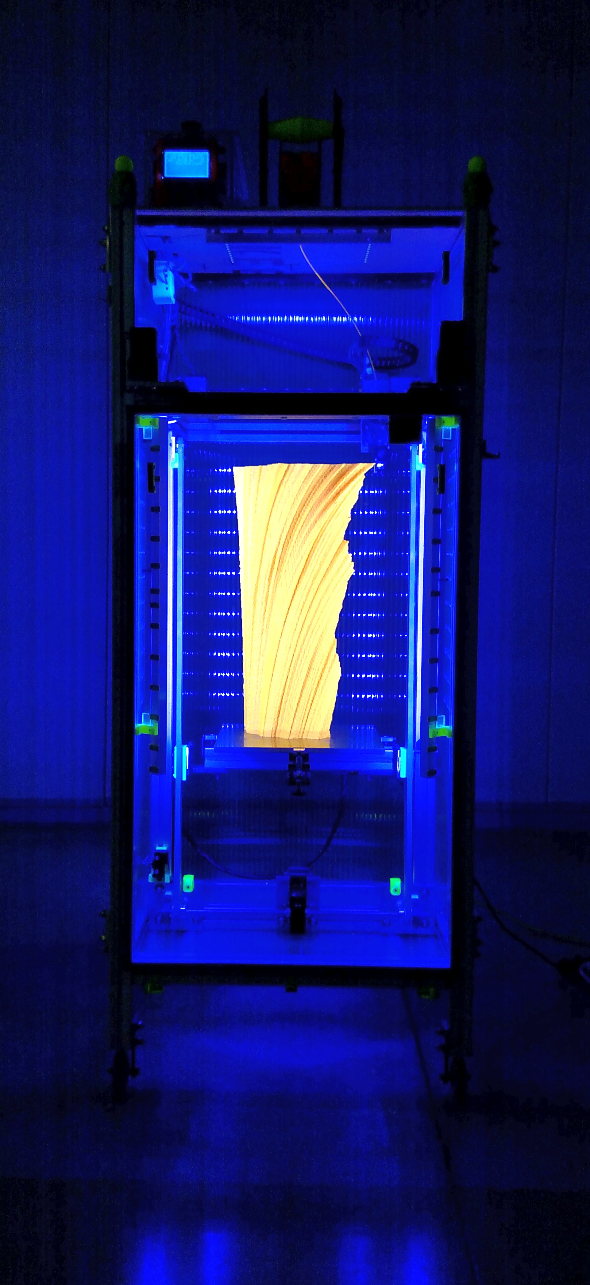
This one made it all the way to 500 mm with only a couple minor issues.

This was made using transparent ABS which looks like frosted glass when it prints, and transmits light very nicely.  I used a 0.6 mm nozzle on the extruder, printed in 0.3 mm layers, 0.6 mm line widths, and printed with 3 shells/perimeters, all at 60 mm/sec.  It's 500 mm tall, took about 39 hours to print and used 781 g of filament.


466 mm, on its way to 500 from Mark Rehorst on Vimeo.

I'm not sure why the slicer has the extruder going all over the place like that, so there may be more tweaking to do, but this one is definitely a success.

I still have to mount it on some sort of base, and add a light source, but here's what it looks like with an LED flashlight lighting it up from the inside:


Unlike a single walled vase, this thing can be handled without worrying about it breaking apart.

When the vase was removed from the print bed, the bottom layer had a couple small cracks, possibly because the 95C bed temperature was a little higher than it should have been for almost 40 hours.  I'll drop the bed temperature a little more for the next one.

There are a couple small layer separations on the back side which may have been because the temperature inside the printer was a bit too cool for ABS.  ABS is usually OK with 45-50C but during this print the temperature in the enclosure was only about 38C.  When I drop the bed temperature, it's going to be even cooler inside the enclosure, so I'll be adding a heater to make it a little warmer in there.

This could be printed with PLA and the layer separation issues would probably go away, but I have to make sure that the print is never subjected to heat, either from a light source or from being transported and left in a hot vehicle.

How I created the model


I started with a program called ChaosPro to generate a Julia set fractal.  After tweaking the parameters for a while I found a shape that I liked, then created an image series that varied one of the parameters of the fractal over a specified range of values.  That left me with 500 or so images.

Next, I opened ImageJ and used it to stack the images to make a solid object from them, then exported the STL file of that solid.

It's all explained in step by step detail here.

I liked the rough texture that resulted from the process, so I skipped the smoothing that the guy did using Blender.

I have tried to print this model using Slic3r's spiral vase mode but it seems to choke on the STL file (maybe the surface is too rough in some places and slic3r can't follow it) and does strange things that wreck the print.  I've been using Cura to slice it, and Cura applies some sort of minor smoothing that leaves most of the rough texture intact but fixes the problems that trip Slic3r.


Thursday, September 28, 2017

This Is What Can You Do With a 3D Printer, No. 1

Here's a project I did about 11 years ago, years before I built my first 3D printer.  It's a Van De Graaff generator (VDG) that produces about 400 kV (that's enough to thrown painful sparks about 300 mm in dry air!).


I never liked the look of the wood box on the bottom, and it was all a little heavy, so a few months ago I decided to update the design.

I redesigned the base and rollers to be 3D printable and found a small DC motor that could be mounted on the base without the big wood box.  The rollers use bearings pulled from hard disk drives.  I printed the parts using PLA.

Full details and CAD and STL files are available on Instructables.

I took it to the Milwaukee Maker Faire last week just to show what can be done with a 3D printer, and after it sat unnoticed for a few hours, decided to move it closer to foot traffic and plug it in.  If you ever want to attract kids to a booth at a product show or Maker Faire, just bring along a VDG!  As these people demonstrated a Van De Graaff generator can be a lot of fun!

I suspect this was Kylee's favorite thing at the Maker Faire.  She spent a lot of time with us!


Fun for all!


3D Printed VDG Hurting My Fist from Mark Rehorst on Vimeo.

 In the photos below I used a 30" exposure time and high ISO, then boosted the brightness and contrast to get what you see.  The photos don't quite capture the blue glow that accompanies each big spark.  The big sparks usually look like a thin, bright line surrounded by a pale blue cloud.


Photographing the sparks is a little tricky.  I prefocused the camera with the lights on, then shut off the lights and opened the shutter for 30 seconds.  IRIC, the camera was set to ISO 3200 and f4.  While the shutter was open I walked over to the generator and moved my hand around near it and got the sparks to jump.  That faint purple glow you can see surrounding some of the bigger sparks in the picture is there with every spark.  It just doesn't show up very well in the photos.


3D Printed Van De Graaff Generator with a Plasma Ball Zapping My Hand from Mark Rehorst on Vimeo.

Update 3/8/18

I changed the top terminal from 11" to 14" diameter (still using Ikea Blanda salad bowls) which should allow the generator to hit 520 kV.  It now discharges continuously from the top terminal to the brush on the bottom of the machine, so I slid one of the original 11" bowls down the tube to cover the bottom of the generator and this is what it did:

The distance from the top bowl bottom edge to the bottom bowl top edge is 550 mm.

I still have some optimizing to do- the sharp edges of the bowls have no insulation, so they tend to create corona discharge.  I'll probably get another 14" bowl for the bottom, and maybe a longer piece of pipe...


Tuesday, September 19, 2017

Comparing Gates LL2MR09 and Chinese 2 mm Pitch Glass Core Belts

I recently saw a couple pictures someone posted of two identical prints, made on the same machine with the same gcode file, one using very inexpensive Chinese import glass core GT2 belt and the other using a more expensive Gates belt.  I was impressed by the reduced ringing in the print made using the Gates belt, so I decided to try this experiment for myself.  Unfortunately, I've lost track of the link to those pictures.

I located a source and ordered 50 feet (the minimum quantity that Gates distributors will sell) of the Gates LL2MR09 belt (about $2 per ft. shipped).

One of the things that has always bother me about the Chinese belt was that there are exposed glass fibers along its edges.  Well, the Gates belt has that, too.  Both belts are neoprene with fiberglass core, both 2 mm pitch, and both 9 mm wide.

SKU9396-0052
Part NumberLL2MR09
ProfileGT
Pitch2 mm
Top Belt Width per strand (mm)9
Tensile CordFiberglass
Core MaterialChloroprene
Fabric CoverNylon
RMA Oil and Heat ResistantYes
Min Order Qty50 ft
Max Cont Length (feet)300 ft
Product Number93960052
Weight0.0200
ManufacturerGates
BrandGates

The Gates belt has nylon facing on the teeth which Gates says decreases wear and increases the life of the belt (and pulley?).  Gates also specifies an operating temperature range of -54 to +85 C, so it should be fine inside a heated enclosure for printing ABS.  I was unable to locate any operating temperature range spec for the Chinese belt.

The Chinese belt doesn't seem to have a nylon facing on the teeth, but I can see what appear to be the ends of threads embedded along the tooth surface under a microscope.

Gates belt specs

In the following photos the Gates belt is on the bottom and the generic Chinese belt in on the top.

Chinese belt on top, Gates belt on the bottom.  The gates belt has nylon coating on the teeth.


The chinese belt, top, appears to have fibers embedded in the tooth surface, and the teeth look slightly larger than the Gates belt teeth.  Glass fibers (brown) are visible on the edges of both belts.


Glass fibers are visible in the edges of both the Chinese and the Gates belts.


Notice there are 17 glass cords in the Chinese belt, top, and 20 in the Gates belt, bottom.  Cord diameters appear to be about the same, spacing between the cords doesn't appear to be well controlled in either of them.


One minor difference is that the slicing of the Chinese belt doesn't seem to be particularly accurate.  If you watch the edges of the belt as it moves on the printer, they seem to move up and down as if the top and bottom edges aren't parallel everywhere.  The Gates belt doesn't do that.

I ran some print tests and there didn't appear to be any difference in print quality.  Maybe the parts I printed weren't good for showing the differences.  I'll be trying more prints and if I run into anything that reveals a big difference I'll post it here.  It was enough effort to swap the belts that I don't expect to be doing it again without a really compelling reason.

This video shows one of the test prints- I turned up junction deviation to 0.2 (from 0.05) to induce ringing, and made the straight runs long enough to allow a peak speed of 250 mm/sec.  I used the same gcode with the only difference between the prints being the belts in the XY stage.  To my critical and microscope assisted eye, the prints are essentially identical.  The ringing looks the same, the layer registration at the corners looks the same.  Meh.

UMMD printing ABS at 250 mm/s from Mark Rehorst on Vimeo.


In the short term, these belts seem to perform pretty much the same, but print quality isn't the only criteria by which to judge a belt.  If one belt outlasts the other and the drive pulleys used with one or the other last longer, one belt or the other might be better.