Some people like to dress their printers up with 24 bit RGB variable color LED lighting that they can control from a phone. Meh. I just wanted plenty of light in UMMD so I could see what is happening and to make it easier to do maintenance and repairs, if they're ever needed, and to photograph prints. To that end I installed
two 8W cool white LED strips on either side of the lower front opening of the printer, and two smaller 3W strips on the underside of the top cover. Together they provide plenty of light.
 |
| Plenty of white light! |
I have taken
Son of MegaMax to the Milwaukee Maker Faire for the last couple years and will be taking UMMD this year. One of the more popular events at the Maker Faire is the Dark Room where we set up things that look impressive in the dark. There are always lots of interesting displays done with projectors, LEDs, blacklights, etc. Here's one that's very popular...
Knight in Armor vs Big Tesla Coil from
Mark Rehorst on
Vimeo.
This year I'm planning to have UMMD in the Dark Room for one day of the Faire, so I'm installing UV LEDs and will print something interesting with fluorescent filament. I initially bought some UV LED strips via ebay that worked OK, but weren't as bright as I wanted. So I did some more shopping.
SoM has a 400 nm UV light bar that does a pretty good job, but I always felt it produced too much visible, pale blue light along with the deeper purple that causes the fluorescence. So I looked for shorter wavelength LEDs, hoping they would produce less of the pale blue light. I bought a bunch of 1W 360 nm LEDs on 16 mm diameter aluminum circuit boards and wired some of them to test. I found that 360 nm LEDs cost about 4-5X what 400 nm LEDs cost and both produce about the same pale blue light, and both cause the same fluorescence, so there's no point in buying the more expensive, shorter wavelength LEDs. I also realized that it's a PITA to mount all those round PCBs and then wire them all together.
 |
The UV light bar in SoM is mounted at the top, front of the printer's frame using printed snap-in brackets.
|
|
 |
The UV light has a very nice effect when you use fluorescent filament.
|
|
1W LEDs usually use 350 mA. UV LEDs typically drop 3.4-3.8V each at that current. The easiest way to power LEDs is to connect them to the printer's 24V power supply. 24/3.4 = 7.06 and 24/3.8=6.3, so I needed to find a narrow circuit board that would allow me to connect 6 or 7 LEDs in series, and allow easy coupling to a heatsink. I searched ebay and some of the Chinese sites and found some
300 x 10mm aluminum circuit boards designed to wire 6 LEDs in series. I ordered a 5 pack for $6.
Next I looked for 1W UV LEDs without any circuit boards.
I found a pretty good deal on some 400 nm LEDs so I bought 30 of them for $15.
Finally, LEDs, like other semiconductors tend to drop more voltage as they heat up, which is another way to say that if you operate them from a constant voltage supply, they will take more current. That leads to more heating, which leads to more current, and pretty soon you have a condition known as thermal runaway and your LEDs burn up.
The best way to avoid thermal runaway is to power LEDs with a constant current source. You set the current to 350 mA for a string of 1W LEDs and they all get 350 mA and it doesn't matter if the LEDs heat up a little, the current source automatically adjusts its output voltage to maintain the set 350 mA. They also maintain constant brightness when you use a constant current source.
This works great for a few LEDs, but if you're trying to run 30 UV LEDs at 350 mA, you need a current source that can deliver up to 30 x 3.8V = 114V. That's a problem if you only have a 24V power supply. You can probably find an expensive boost converter that will provide a constant current, high voltage output, but there are other ways.
Since UMMD has 24V available (I'd prefer not to run another 117 VAC supply), I can drive up to 6 LEDs in series (6 x 3.4V = 20.4V). I have 5 circuit boards with 6 LEDs in series on each, so all I have to do is wire the circuit boards in parallel. Since each board needs 350 mA, I could use a constant current supply that delivers 350 mA x 5 =1750 mA. But what happens if an LED dies? Now there are 4 boards sharing 1750 mA- they all get brighter for a while, then they probably burn up. So constant current isn't the best way to power LEDs wired in series-parallel.
Powering LEDs from a constant voltage isn't ideal, but it is easy/cheap when you're using a low voltage power supply.
I found a 35W buck converter that will take the 24V input and convert it to a voltage/current limited output for $8. This device can be operated as a constant current source by setting the voltage output to maximum and then adjusting the current limit pot for whatever current you want up to 3A. Or, it can operate as a constant voltage source by turning the current limit all the way up and setting the output voltage you want up to about 22V. Or you can operate it in between, and set both voltage and current limits.
I had my LEDs, and my power source, now I just had to mount them. I used some 3/4" x 3/4" aluminum L stock. It was rigid and could be mounted easily, and serves as a light guide that blocks the direct view of the LEDs when looking at the printer from the front. I mounted the PCBs on the aluminum L using some printed ABS clips. They snap on and hold the aluminum PCB in tight contact with the L stock, transferring heat away from the LEDs.
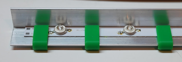 |
Aluminum LED PCB mounted on 3/4" x 3/4" aluminum L as a heatsink/mounting bracket/light guide, using printed ABS clips. The clips hold the PCB tightly against the L to ensure efficient heat transfer.
|
|
 |
| One of the printed ABS PCB clips. It snaps on tightly, ensuring heat transfer from the PCB to the L heatsink. |
 |
| One of two 12 x 1W UV LED light bars that will be mounted vertically on the front of the printer. The bright green objects are the brackets that snap into the t-slot frame of the printer. The white LED bars will be mounted alongside the UV strips. |
I found that the heatsink got pretty warm if I operated the LEDs at full power, so I dropped the voltage a bit and gave up just a little of the brightness in exchange for much cooler operation. I set the buck converter for about 19.6V output and limited the current to 1.3A. The voltage setting limits the current through the LEDs initially to just over 1A. If the LEDs heat up because they are inside a warm printer enclosure, they'll try to suck more current from the buck converter, and when it reaches the set limit, the converter will operate in constant current mode and that will prevent thermal runaway.
Here's a short video of the printer putting down some fluorescent yellow filament with the lighting switched between the white and UV LEDs.
UMMD 3D Printer White and UV Lighting from
Mark Rehorst on
Vimeo.
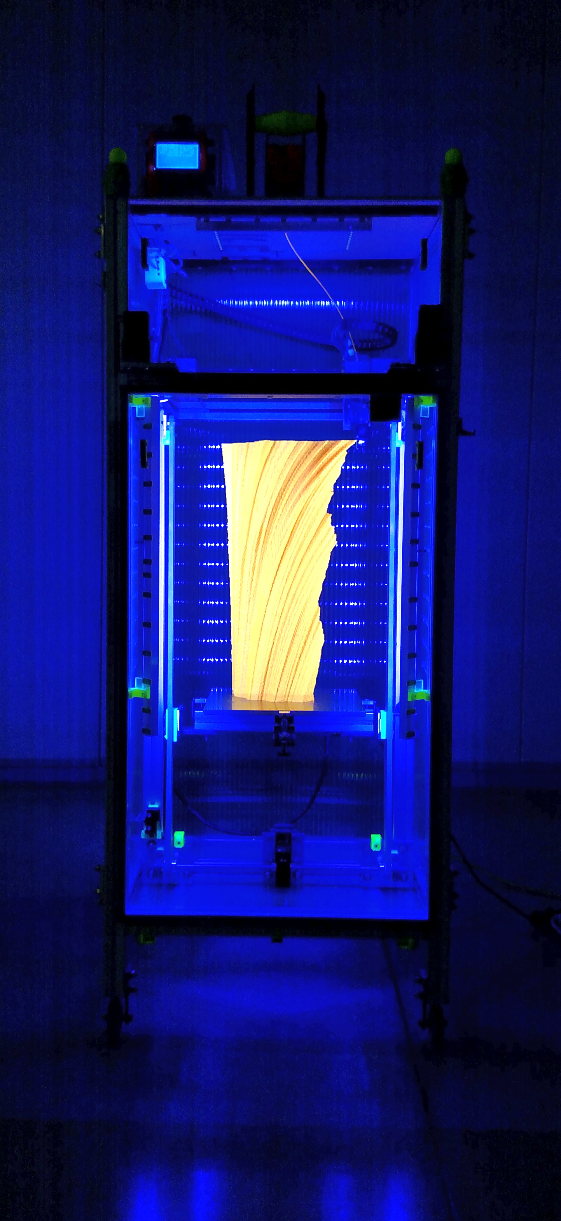
Here's a still photo in which I tried to tweak the exposure to match what the eye sees when the UV lights are lighting up a fluorescent yellow print. The photo just doesn't do it justice- in real life it's almost painful to look at the print because it glows so brightly.