Update 5/30/22
I found a site where someone did a complete teardown of one of the iHSV57 motors with lots of photos.
After struggling to get JMC1.7.6 software working in Windows 10 (I kept getting error messages about a log file from Microsoft .NET), and trying and failing to get it working in Windows 11, I decided to try using Robert Budde's python tool available on Github here. I struggled to get it working in Windows 10, and decided to try linux instead. I loaded the prerequisites on my old netbook that I use to communicate with the printer (Lubuntu 20.04) and then ran the program and it worked on first attempt. I am finally able to actually tune the motors!
The python tool displays the parameters and an oscilloscope similar to the JMC program, so information about tuning in videos linked below is still applicable, you just have to make some allowances for where and how the information is displayed.
When the program is running, you have a choice of selecting iHSV57 v5x or iHSV57 v6x motors. I found that the iHSV57 v6x selection allows me to communicate with the IHSV42-40-07-24 motors I am using in Arrakis and testing in UMMD. The iHSV57 v5x didn't work at all with my motors.
Update 5/29/22
I found two new videos in English, that explain how to tune these motors for CNC applications using the JMC software:
Update 5/27/22
I opened up one of the motors to see what I could see.
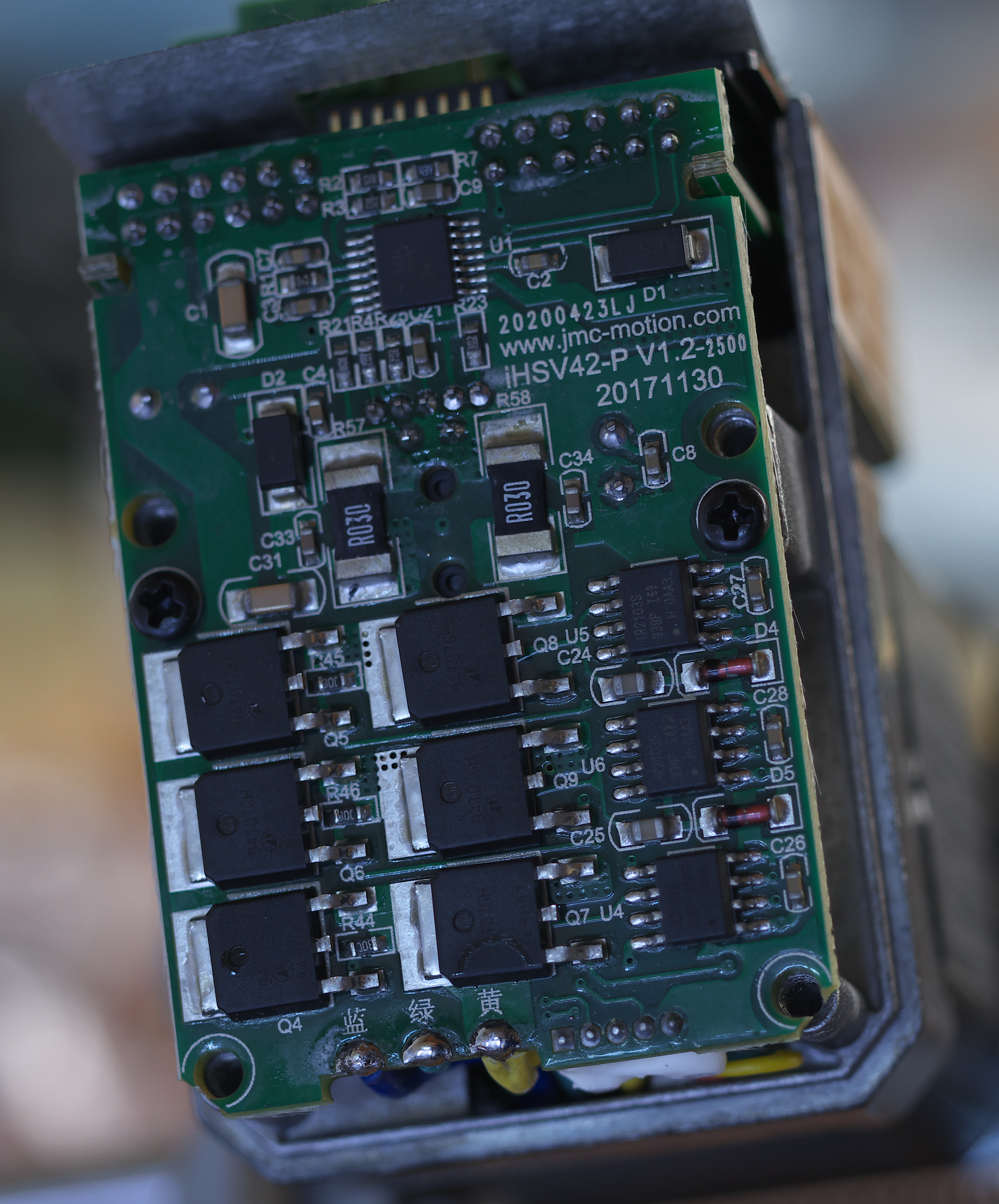 |
| One of the circuit boards. The aluminum cover that fits over this piece has a thermal pad that contacts the driver power transistors to help cool them. |
 |
| Look at that! It's actually an optical encoder! |
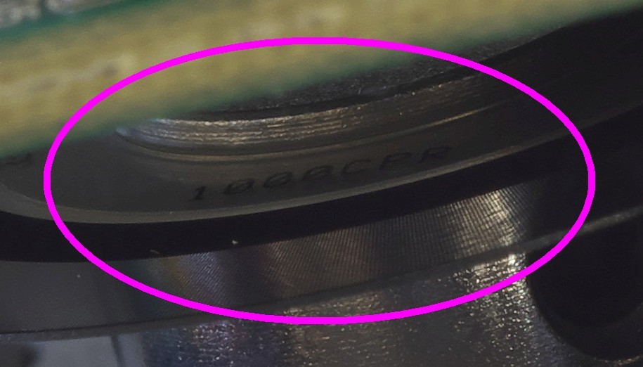 |
| Close-up of the markings on the encoder wheel- 1000 CPR (counts per rev?) |
I have produced a PCB for the returned energy dump circuit detailed below. See: https://drmrehorst.blogspot.com/2022/05/bank-account-protection-circuit-for.html
Update 3/30/21
I had a disaster with the sand table. Details in this post. The long and short of it is that the motor(s) was forced to make an abrupt stop that created a voltage spike on the power supply line, killing both the controller board and the power supply. This sort of phenomenon is well known in the servomotor world and there are engineering solutions such as this, courtesy of Gecko Drive:

There's a pdf that describes the circuit operation here. I recommend if you're going to play with servomotors that you take all precautions to protect your controller and the motor drivers.
Now back to the original post...
I recently ordered a couple iHSV42-40-07-24 78W servomotors from China with the intention of trying them in the sand table and probably also UMMD. There isn't a lot of information on these things out there, and I spent quite a while searching, so I decided to place everything I found here so others may be able to make easier use of the motors.
The motors all appear to be made by Just Motion Control in Shenzen, and are sold by many companies that list on ebay and Ali-express. The specific motors I ordered are NEMA-17 size, but the same controller is found on NEMA-23 and NEMA-34 size motors, too. One manual covers all of them.
The motor driver accepts 5V step/direction/enable signals like many stepper motor drivers, so you can drive these motors using anything you would use to drive a stepper. I spotted this device in a youtube video and it appears to be very useful for anyone who might be playing with either stepper or servomotors of this type:


You can find them on ebay for about $15. There are other parts with similar function, but this type can handle supply voltages up to 160VDC so you won't need a separate power supply to power this device for almost any stepper or servo motor you may be testing. Here's a link to an ebay search that will take you to this type device.
I made a Fusion360 CAD model of the iHSV42-40-07-24 that you can download. It is primarily useful to get the overall size, but details such as the mounting hole spacing, length of the shaft, etc., are accurate enough to design mounts. When I found differences between the actual motor and the drawing in the manual, I used measurements from the motor itself, so the CAD model is of the specific motors I received from China. As always, what you recieve from China may be slightly different!

To get optimum performance from the motors, you have to tune them for your specific application. That is accomplished by making an RS-232 serial connection to the motor and then using software that JMC provides to tweak about 100 different parameters.You can use a USB to serial converter of this type to make the connection, You can use a USB to RS-232 adapter of this type if your computer doesn't have a DB-9 serial port. Any adapter that says it uses a PL2303 chipset should work. The motors have spring terminal connections for wires, not a DB9 connector, so you'll have to either cut up an old serial cable or add a few wires to a DB9 socket so you can connect to the motors. You only need to connect the Tx, Rx, and Gnd leads from the RS-232 cable to the motor. Be sure to connect the Tx output on the cable to the Rx on the motor, and the Rx on the cable to Tx on the motor. If you can't get the computer to talk to the motor, try swapping the Tx and Rx connections, most easily done at the motor.

The motors all appear to be made by Just Motion Control in Shenzen, and are sold by many companies that list on ebay and Ali-express. The specific motors I ordered are NEMA-17 size, but the same controller is found on NEMA-23 and NEMA-34 size motors, too. One manual covers all of them.
The motor driver accepts 5V step/direction/enable signals like many stepper motor drivers, so you can drive these motors using anything you would use to drive a stepper. I spotted this device in a youtube video and it appears to be very useful for anyone who might be playing with either stepper or servomotors of this type:


You can find them on ebay for about $15. There are other parts with similar function, but this type can handle supply voltages up to 160VDC so you won't need a separate power supply to power this device for almost any stepper or servo motor you may be testing. Here's a link to an ebay search that will take you to this type device.
I made a Fusion360 CAD model of the iHSV42-40-07-24 that you can download. It is primarily useful to get the overall size, but details such as the mounting hole spacing, length of the shaft, etc., are accurate enough to design mounts. When I found differences between the actual motor and the drawing in the manual, I used measurements from the motor itself, so the CAD model is of the specific motors I received from China. As always, what you recieve from China may be slightly different!
 |
| Fusion360 model of the iHSV42-40-07-24 motor. |
 |
| Printed motor mount for the sand table that I designed around the CAD model of the motor. There's an F625 bearing in the top of the mount to support the free end of the motor shaft. |

To get optimum performance from the motors, you have to tune them for your specific application. That is accomplished by making an RS-232 serial connection to the motor and then using software that JMC provides to tweak about 100 different parameters.
Software to tune the motors is here. Plug n your USB to RS-232 cable, then unzip and run JmcServoPcControl.exe
Before you can tune parameters, you have to get your computer talking to the motors. The manual says the default communication speed is 9600 bps, but my motors were factory programmed for 57,600 bps, 8 data bits, even parity, and 1 stop bit. The first thing to do when you open up the motor programming/monitoring software is to set the serial communications parameters. Once you get the software talking to the motors, there will be a few green lights on the bottom of the window in the software indicating that the motor is on-line. Then you can start tweaking parameters.
The manual for the motors is mostly useless other than to show what all the parameters are- there's no information about tuning procedures. I found that the software provides a bit more information about the parameters and clues to the settings, but you have to connect to a motor to be able to see that stuff. I grabbed screenshots of every page defining the parameters in the software and put them together in a zip file that you can download here. The individual pages are labeled for the specific parameter numbers they define so it is easy to find the one you're looking for. I may have altered some of the parameter values before I captured the pages, so you may see something a little different the first time you connect to your motors.

How do you know what to tune? There's the rub! I found some useful information on tuning servomotors at these sites:
http://s3.cnccookbook.com/CCServoTuning.htm
https://www.machinedesign.com/archive/article/21827276/tuning-servomotors
http://s3.cnccookbook.com/CCServoTuning.htm
https://www.machinedesign.com/archive/article/21827276/tuning-servomotors
Parker Motion Servo Fundamentals
There appears to be three main operating modes for the motors, speed, position, and torque control modes, selected by the P01-01 parameter (see image above). The motor driver has some autotune modes built in to simplify the tuning process. If you enable one of those modes, the driver will make adjustments on the fly to optimize performance for speed, positioning, or current. Check page 19 of the motor manual for the P01-02 parameter setting. Once you've selected an operating and autotuning mode, there remains just a few variables to adjust manually. The Parker Motion white paper linked above has a pretty easy to understand explanation of the process of tweaking the remaining variables.
There appears to be three main operating modes for the motors, speed, position, and torque control modes, selected by the P01-01 parameter (see image above). The motor driver has some autotune modes built in to simplify the tuning process. If you enable one of those modes, the driver will make adjustments on the fly to optimize performance for speed, positioning, or current. Check page 19 of the motor manual for the P01-02 parameter setting. Once you've selected an operating and autotuning mode, there remains just a few variables to adjust manually. The Parker Motion white paper linked above has a pretty easy to understand explanation of the process of tweaking the remaining variables.
I ran into a few youtube videos of people doing various things with the NEMA-23 and 34 versions of the motors. There's a good series of videos, in German, that go into some detail about tuning the motors for a CNC machining application:
Wonderful summary, many thanks!
ReplyDeleteOn my next project, I'll be consulting this :-D
Thanks! I wish I could find some English language information on tuning procedures for these motors...
DeleteThanks for putting this together! I wanted to download your model, but I only get to the fusion web preview, is there another way to share it?
ReplyDeleteI also found this video, if you haven´t seen it:
https://www.youtube.com/watch?v=ompFVlYOqXU
Yeah, Fusion360 doesn't work the way it used to. I'll update the link in the post above with a new link to the Fusion360 archive file.
DeleteThat's another good video, but like the others, there's no real explanation of which parameters relate to which behaviors in the motors. I think you'd need a model of the control system in order to know which parameters to tweak for different motor applications.
I've looked at some other servomotor driver tuning videos and find that different manufacturers use different control schemes so the variables to tune are all different. I think what's really needed is a Chinese manual on the control scheme and someone to translate it to English.
Thanks a lot for the model! I´ve seen your amazing sand drawing machine now, great use for these motors!
DeleteI´m from Germany, and here the bigger nema23 motors are used a lot in cnc´s. So I do have them on my cnc too. The version I got is older, so is the jmc-software.. but there is a github project with a better and faster tuning interface, but i don´t know if it still works with the 5xx firmware. (https://github.com/robert-budde/iHSV-Servo-Tool)
Maybe I can give you some feedback after tuning my nema17´s.
I saw that software but couldn't quite make out how to use it. For me the biggest problem is a lack of a model of the control system so I can relate the variables to what they do to the motor behavior (and a complete lack of experience with these things). If you know where to get more information (preferrably in English), I'd love to hear it.
DeleteSorry, I messed up my blogger accounts..
ReplyDeleteYes, I found it unsatisfying not to know what I´m really doing when tuning my CNC servos, but I used some baseline parameters from others.
I can tell you what he´s doing in the video I posted above..
He´s getting oscillations / motor noise in (his preffered) auto tune setting.
He found out, that the auto-tuning presets are just some predefined values so he noted down the "auto-tuning" parameters and comapered them:
13-18 has none to high vibrations, the stiffnes goes from low to high and the overcompensation goes from yes+slow to small+fast.
So he´s liking the auto-tuning number 18, but want to use the P08-20 (Torque command filtering constant) value from preset 14 to get rid of the noise.
he´s doing it by loading auto-tune 18, storing it, turning off auto-tuning and changing the P08-20 value manual.
Keep in mind that his table of values is for the bigger servos, but in general it is maybe a good idea to just play with those parameters from the auto tuning, because they seem to have the most impact and we can get a range that seems to be practical.
As i remember tuning my CNC servos, I just watched at the commanded and actual position and the position error value. I upped the P-value to something where the two positions are matching fast (low error value) and the motors are stiff enough, then i played with the I-value to get rid of overshooting, and the filter value was used to get rid of overcompensation. Acceleration and decellaration was upped without getting too much of an current draw not triggring an servo error. - This all could be kind of wrong, because it´s years ago, but I will play with the nema17´s the next weeks, so I can defenitly tell you more then.
I tried to use these motors in my 3D printer (see: https://drmrehorst.blogspot.com/2020/11/heres-what-happened-when-i-swapped.html) and got terrible results. With a "1000 line encoder" I expected much better resolution. Do you know if there's some driver parameter that will improve the result? Someone else used the same motors with 3:1 mechanical reduction and got good results.
DeleteHello! You said "then i played with the I-value to get rid of overshooting", which parameters actually are these which is affecting I-values?
Delete