You know, when I see reviews of audio equipment on the web or youtube, I like to see the guts of the item being reviewed. You can learn a lot about the quality of the device by seeing how it is built on the inside, what sort of components are used, how it's wired, etc. Unfortunately, not many reviewers show the insides of the items being reviewed. I don't have a problem showing them...
 |
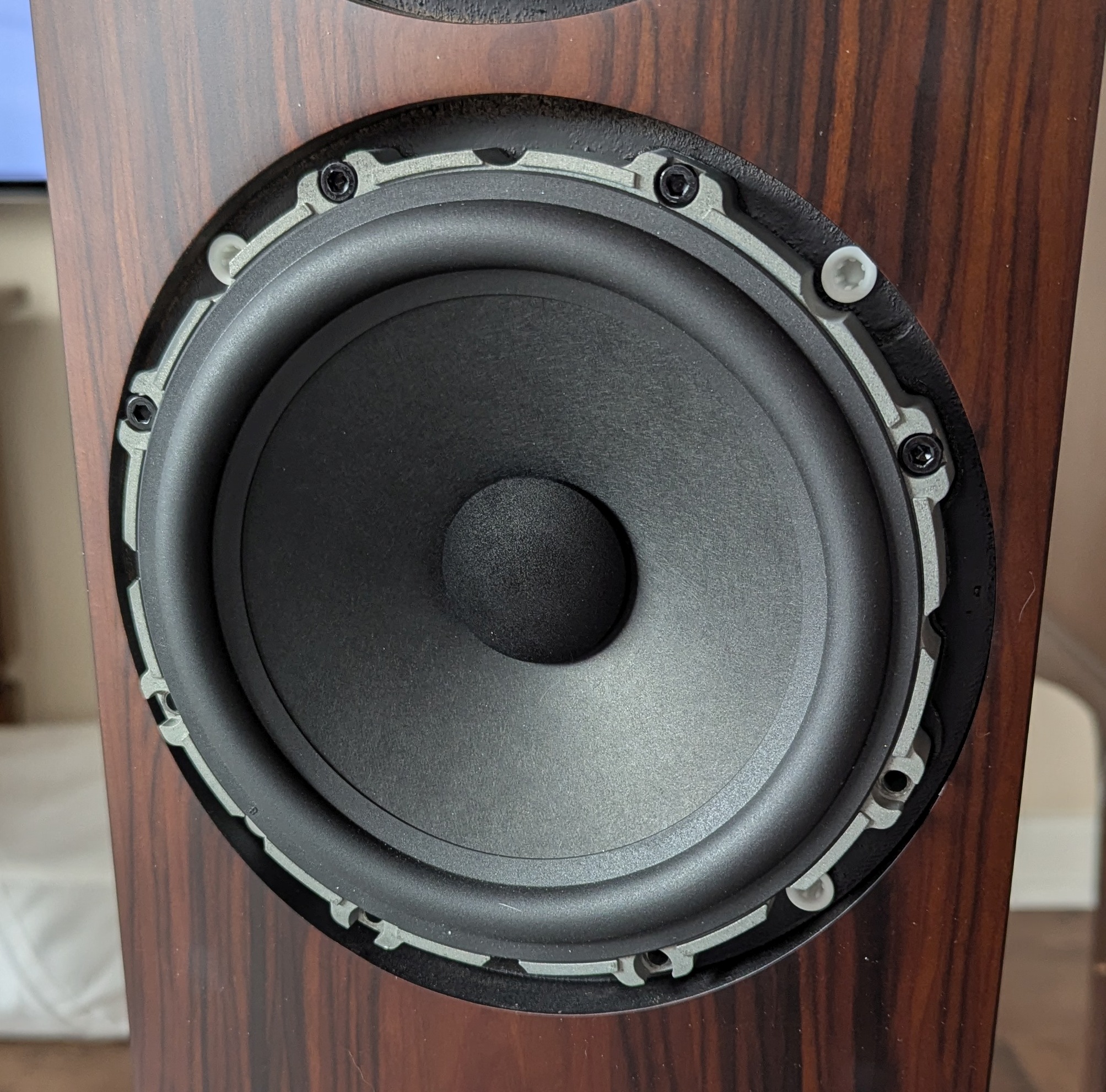
| This is my B&W 703 S3 speaker. There are many like it, but this one is mine. |
I have a pair of B&W 703 S3 speakers. B&W likes to show off exploded views of the drivers, especially the tweeter, but I have never seen any photos or schematics of the crossovers either at B&W's web site or at any of the many reviews scattered around the web. You'd think that B&W would be showing off the crossovers if they were really nice, so are they hiding something?
I decided to open one of my speakers and see what I could see.
First I checked out the wire connections to the terminals at the back of the speaker, hoping the crossovers would be mounted on the terminal plate, but no such luck. I wonder why they don't do that...There are 4x T-10 screws holding the plate in.
 |
| The input terminal plate is held in by 4x T-10 screws. Blue and brown wires are the bass inputs, black and red wires are the mid/high input leads. For those of you who care about such things, some of the hardware at the speaker terminals is magnetic. |
Getting to the crossovers requires removing the bass drivers. First you have to pull off the decorative rings that cover the 8x M4 screws holding each of them into the box. The bass xover is located behind the lower bass driver, and the mid/high xover is located behind the upper bass driver. Each of the crossover boards is mounted on the back of the box with 4x + head screws. The wires that go to the drivers are soldered to the xover boards, but use gold plated Faston connectors on the drivers and at the terminals on the back of the speaker.
 |
| The decorative rings and some of the screws for the bass drivers. |
 |
| The lower bass driver has a nice, heavy, cast aluminum basket. |
 |
| Lower bass driver connections. The two Faston connectors are different sizes, so you can't connect them in reverse. Look at the size of the magnet! |
The stuffing behind the lower bass driver. The bass xover is located behind that piece of stuffing at the back of the box.
 |
| The bass xover. It looks like two ferrite(?) core inductors, one resistor (on the heatsink), and 1 NP electrolytic cap bypassed by 4 film caps. |
 |
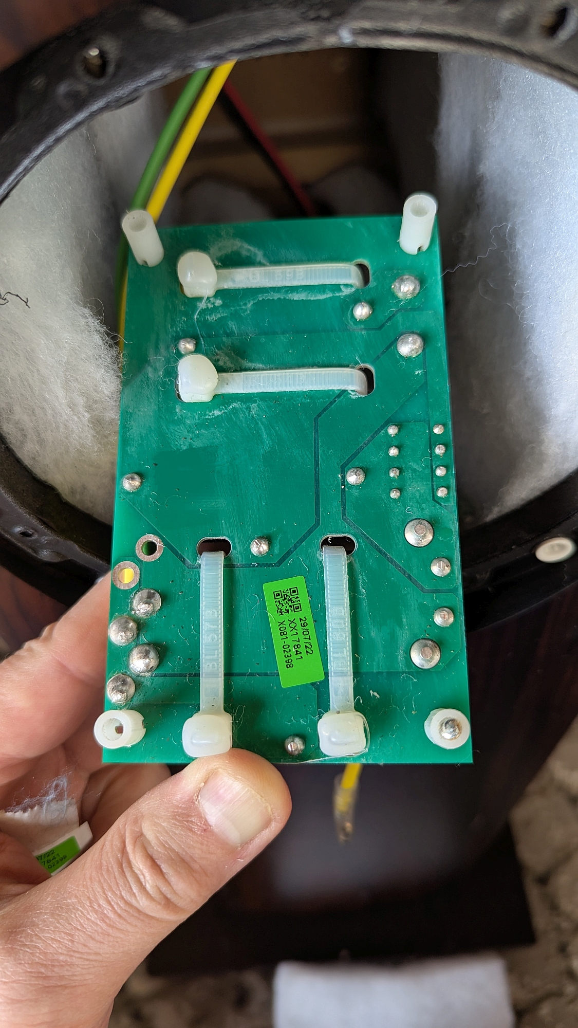
| Back side of the bass xover PCB |
 |
| Bass xover, resistor side view. That looks like a 0.5 Ohm resistor to me. |
 |
| Bass xover, output side view |
 |
| Bass xover, bottom side view. You can see the inductor is 2.8 mH and the film caps (yellow) are 10 nF each. Unfortunately, I can't see the value of the other inductor as it is hidden behind the heat sink. |
 |
| Bass xover PCB pads and circuit nodes. Red circle- input, blue square- film caps, orange square- resistor, green circle - output connections. |
 |
| Bass xover schematic. I was able to measure the inductor whose value was obscured by the resistor, and I checked the DCR of the other inductor while I was at it. |
Update: I disconnected the bass drivers and was able to test the mystery inductor- it reads 1 mH and 0.12 Ohms resistance. While I was at it, I tested the 2.8 mH inductor and found resistance to be 0.2 Ohms.
 |
| The lower bass driver, should be identical to the upper bass driver. Note gold plated (copper?) terminals, big magnet, cast aluminum basket. It looks like a high quality driver! |
I'll add the mid/high xover stuff later. Check back again soon. In the meantime, here's a teaser:
 |
| The mid/high frequency crossover. Quality caps and air core inductors. Nice! |
More photos of the mid/high xover:
 |
| Bottom of the mid/high xover board. |
Unfortunately, the mid/high xover is a pretty complicated circuit using a double sided PCB, and the large components on the top side of the board obscure the pads on the PCB making it all but impossible to trace out the circuit without taking the parts off the board. I'm not going to do that, so what you see is what you get.


Great Job, thank you for sharing
ReplyDeleteSehr interessant, vielen Dank und beste Grüße aus Chemnitz/Deutschland
ReplyDeleteGreat post, thanks.
ReplyDeleteI also have the 702 S3 speakers. Did you, or do you plan to upgrade any of the capacitors on the two cross-overs? I would love some guidance and feedback about what to swap. I do solder and stuff, but my knowlegde of Xover functionality is nearly layman-ish..
What are you trying to achieve, and what makes you think that changing capacitors will achieve it? Are you dissatisfied with the sound the speakers produce? I trust the engineers to have selected good parts for the job. I'll think about replacing electrolytic caps in 20 years if I'm still around and still have these speakers then.
DeleteI read about some who replaced the 120 microfarad in the LF Xover, and the 47 microfarad in the MF_HF Over with a Jentyen superior Z-cap, with the objective to get more out of the speakers. That was my question. Essentially, I do like the sound of my speakers but could they sound better with higher end caps? I am not sure if I want to risk this though because if the sound screws up, I would hate myself..
DeleteWhen you replace caps you're trying to replace non-ideal caps with closer to ideal caps. The non-ideal aspects of the caps (parasitic inductance, for example) mostly affect high frequency performance. So I don't think there's much to be gained by replacing the 120uF cap in the bass filter because the non-ideal behaviors of that cap probably fall outside the frequency range over which it is used.
DeleteThe 47 uF cap is a polypropylene film cap that's already pretty good. You'd be replacing it with another film cap. Not sure what there is to be gained doing that.
The crossover parts are thoroughly modeled and many simulations run by the engineers at B&W. Then they build prototypes and make measurements to verify simulation results and listen to the speakers. I suspect they do a pretty good job selecting the parts to use within their allocated budget.
I've seen people go really nuts over crossover caps and air core inductors and end up with a crossover that's 2-5x the volume of the original. If you make such a large change inside the speaker cabinet you're bound to throw the box tuning off and affect the bass response.
You could replace the caps and if you don't like the result, put the originals back in. In that case you'll be out the cost of the new caps. You'll be expecting to hear an improvement, so you probably will, whether it exists or not. What would be really interesting is if you put both caps in and have a switch so you can instantly switch them, preferably from your listening position.
Replacing the 120uF with e.g. a high end Jantzen component will provide much more dynamic and round base responds - Ive done so on my 702 S2s. Replacing the 47uF cap which is part of the mid-range filter with a high-end Mundorf MCAP EVO Silver Gold Oil gives a distinctively different, IMO higher resolution and dynamic sound - again did so on my S2s. The S2s mid driver is not fantastic, so I also replaced them with 801/2 D4 units (which I suspect are the same as used in the 702 S3 series - I compared them side by side) which gave much better stage. With above mods my S2s IMO have better low and midrange sound than the S3 standard speakers (S3 signatures are different beasts - crossovers are a different level), but the S2s tweeters are still miles behind the S3s, which appear very close to those on the 800 D3 series (have compared side by side). However, just the components to do those mentioned upgrades will add 30-50% cost to the speakers - Mundorf caps are costly as are the 800-series mid-range drivers.
ReplyDeleteThanks for the comments.
DeleteThis sort of subjective stuff is a problem for me. One person hears things one way and another hears them another way. Peoples' hearing is influenced by expectations, visual cues, peer pressure, etc. What is "dynamic and round bass" and how would you measure it objectively? Without objective measurements, there's really no way to quantify a change in performance linked to a change in components. I don't know what you were expecting to hear when you changed the caps, but I know you were expecting to hear something, because you went to the trouble and expense to make the change. You may have heard a real change, or your expectations may have led you to hear a change that wasn't there.