Showing posts with label crossover. Show all posts

Thursday, April 3, 2025

B&W 703 S3 crossovers

You know, when I see reviews of audio equipment on the web or youtube, I like to see the guts of the item being reviewed. You can learn a lot about the quality of the device by seeing how it is built on the inside, what sort of components are used, how it's wired, etc. Unfortunately, not many reviewers show the insides of the items being reviewed. I don't have a problem showing them...


This is my B&W 703 S3 speaker. There are many like it, but this one is mine. 


I have a pair of B&W 703 S3 speakers. B&W likes to show off exploded views of the drivers, especially the tweeter, but I have never seen any photos or schematics of the crossovers either at B&W's web site or at any of the many reviews scattered around the web. You'd think that B&W would be showing off the crossovers if they were really nice, so are they hiding something?

I decided to open one of my speakers and see what I could see.

First I checked out the wire connections to the terminals at the back of the speaker, hoping the crossovers would be mounted on the terminal plate, but no such luck. I wonder why they don't do that...There are 4x T-10 screws holding the plate in.


The input terminal plate is held in by 4x T-10 screws. Blue and brown wires are the bass inputs, black and red wires are the mid/high input leads. For those of you who care about such things, some of the hardware at the speaker terminals is magnetic.

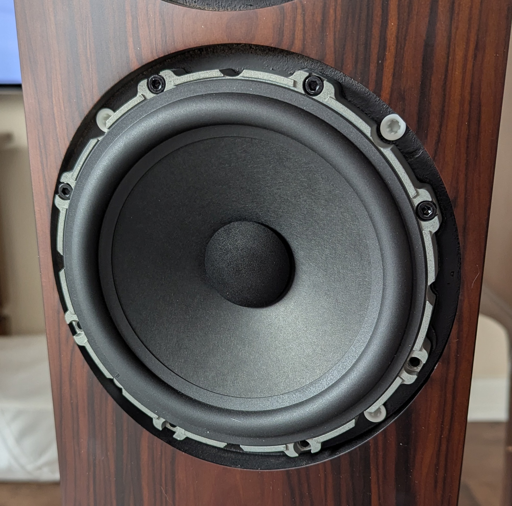
Getting to the crossovers requires removing the bass drivers. First you have to pull off the decorative rings that cover the 8x M4 screws holding each of them into the box. The bass xover is located behind the lower bass driver, and the mid/high xover is located behind the upper bass driver. Each of the crossover boards is mounted on the back of the box with 4x + head screws. The wires that go to the drivers are soldered to the xover boards, but use gold plated Faston connectors on the drivers and at the terminals on the back of the speaker.


The decorative rings and some of the screws for the bass drivers.


The lower bass driver has a nice, heavy, cast aluminum basket.


Lower bass driver connections. The two Faston connectors are different sizes, so you can't connect them in reverse. Look at the size of the magnet!


The stuffing behind the lower bass driver. The bass xover is located behind that piece of stuffing at the back of the box.


The bass xover. It looks like two ferrite(?) core inductors, one resistor (on the heatsink), and 1 NP electrolytic cap bypassed by 4 film caps.


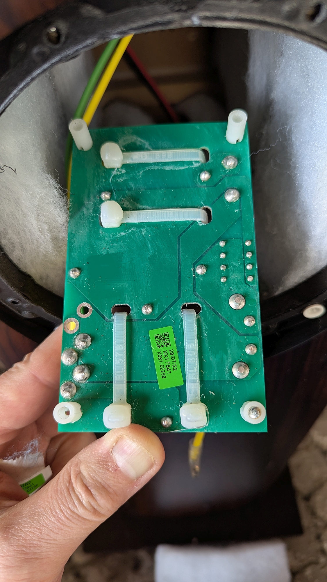
Back side of the bass xover PCB


Bass xover, resistor side view. That looks like a 0.5 Ohm resistor to me.


Bass xover, output side view


Bass xover, bottom side view. You can see the inductor is 2.8 mH and the film caps (yellow) are 10 nF each. Unfortunately, I can't see the value of the other inductor as it is hidden behind the heat sink.


Bass xover PCB pads and circuit nodes. Red circle- input, blue square- film caps, orange square- resistor, green circle - output connections.


Bass xover schematic. I was able to measure the inductor whose value was obscured by the resistor, and I checked the DCR of the other inductor while I was at it.


Update: I disconnected the bass drivers and was able to test the mystery inductor- it reads 1 mH and 0.12 Ohms resistance. While I was at it, I tested the 2.8 mH inductor and found resistance to be 0.2 Ohms. 


The lower bass driver, should be identical to the upper bass driver. Note gold plated (copper?) terminals, big magnet, cast aluminum basket. It looks like a high quality driver!


I'll add the mid/high xover stuff later. Check back again soon. In the meantime, here's a teaser:

The mid/high frequency crossover. Quality caps and air core inductors. Nice!

Those Mundorf caps are supposed to be pretty good. They'd better be for what they cost. It's nice to see that B&W didn't skimp on the crossovers or the drivers.

More photos of the mid/high xover:

Bottom of the mid/high xover board.


Unfortunately, the mid/high xover is a pretty complicated circuit using a double sided PCB, and the large components on the top side of the board obscure the pads on the PCB making it all but impossible to trace out the circuit without taking the parts off the board. I'm not going to do that, so what you see is what you get.


Friday, June 28, 2024

Another Recapping Project: Canton Ergo 22DC Speakers


Canton Ergo 22DC speakers and SVS 3000 Micro subwoofer.

Do you collect vintage audio gear? Or maybe you just have some stuff you've been using for years and it seems to work just fine. Over all the years you've been using that gear, the electrolytic caps have been slowly degrading, maybe doing the same to the sound, but so slowly you haven't noticed. If the gear is more than 20 years old, it's a good idea to replace all the electrolytic capacitors. Yes, even in speakers. Most speakers have at least one nonpolar electrolytic capacitor in the crossover. If you're not sure, open it up and take a look.

My brother recently gave me a pair of Canton Ergo 22DC speakers that look and sound great, but they are over 20 years old. I opened one of the speakers up and found two 12 uF and one 1000 uF nonpolar electrolytic caps. One of the 12 uF caps measured poorly on my LCR meter. I checked with Canton to see if I could buy replacements from them and the answer was a polite "no- they are no longer available". 

I did some searching and was unable to locate 12 and 1000 uF caps that matched the original part's 5% tolerance. However, I found 10% tolerance parts replacements at Madisound Speaker Components. The new parts are made by a company in Taiwan called MDL and are specifically for audio, whatever that entails. The original parts were rated for 23VAC (I know, weird, right?) and the new ones for 100V. It's OK to go up in voltage, but don't go down! They should last another 20 years.

I checked the new caps with an LCR meter and it showed the 12 uF caps to be 11.6 uF with ESR of  0.06 Ohms at 10 kHz, and the 1000 uF caps read about 991 uF at 100 Hz with <0.1 Ohm ESR, so all were within the 5% tolerance of the original parts.

If you're ever thinking about recapping an amplifier or other piece of gear, and not sure you have the skills, try recapping speakers first. It's pretty easy and hard to mess up!

If you can't find nonpolar capacitors that match the capacitance in your speaker, you can always make a non polar cap by connecting two polar electrolytic caps back to back. For example, if you need a 5 uF non polar cap and can't find one, get two 10 uF polarized caps and wire them like this:


You can connect the caps either way: + to + or - to -. The final value is 1/2 of each cap's value (use the same value for both!). Final voltage rating is the same as each cap's rating- if you use 50V caps, the nonpolar cap will be a 50V cap.


Surgery


In most speakers, you can get at the crossover by removing the bass driver. Just figure out how to take off the grilles without damaging the speaker cabinet's finish and you're half-way there. In the Cantons, the little logo badge at the bottom front pulls out revealing a spot where you can get your fingers under the perforated steel grille to lift it off the speaker.


The patient, prepped and ready for surgery.


Remove the logo badge and the grille.


Take out the woofer- Torx #15 tool required for this speaker.


The stuffing, removed from inside the speaker


The crossover board, held in place by the nuts on the screws that pass through the inductors.


The crossover out of the box- no need to disconnect either the drivers or the input terminals.

I used a desoldering pump and a soldering iron with a large tip to remove the old capacitors, inserted the new ones and soldered them down, and finally clipped off the leads. You don't have to worry about polarity with these caps!


The three new capacitors soldered in and ready to reassemble. Bolt the crossover back in place, replace the stuffing (very important!), screw the bass driver down, vacuum the fuzz off the front panel, and replace the grille.

The total time required, start to finish, was about 15 minutes for one speaker. The new caps cost about $15 per speaker. As long as the adhesives in the drivers hold out, and I don't do anything stupid with the amplifier driving them, they should last another 20 years.


Like Radiohead says, "Everything in its right place..."