Showing posts with label lighting. Show all posts

Wednesday, July 8, 2020

To a Hammer, Everything Looks Like a Nail

A couple years ago I installed a timer switch on my front porch light so it would turn on at dusk and off at dawn. It was one of those smart switches that knows what time it is and when the sun sets and rises and even keeps track of daylight savings time. The light uses two candelabra type bulbs and is about 12' (almost 4m) off the ground. At about the same time I installed the timer, I installed a couple LED type bulbs because they are supposed to last 20 years and I don't like climbing up on a ladder to change light bulbs that are 12' in the air.

Well, it's two years later and one of the so-called 20-year LED bulbs failed. I wanted to replace both of them with yellow bulbs because the white light attracts bugs, and the bugs attract spiders, and the spiders make webs and catch the bugs and leave things looking very messy. I found a couple candelabra base yellow LED bulbs at Home Depot, got out the ladder and went to install the new bulbs.  

The fixture hangs from a chain, way up in the air, and requires two hands to get it apart to install the bulbs. That means I'm up on a ladder, with two hands on the fixture and none on the ladder, not a good situation. I unscrewed the bottom part of the lamp fixture, and it and the glass then came down, granting access to the bulbs. I had forgotten that the glass doesn't actually attach to the bottom part of the fixture and ended up dropping it. Oops!

So now I had to replace the glass, an impossible task because that stuff is not standard and even if I could figure out who made the lamp, they've long since stopped making them or stocking the glass parts. So my choices were either buy a whole new fixture or make my own replacement for the broken glass. Being a cheapskate and 3D printing type person- you know the type, every problem can be solved with a 3D printer- and having recently made a nice lamp using some beautiful edge-glow glass PETG filament from Keene Village Plastics, I decided to try using the stuff to make a replacement for the broken glass. If it didn't work, I'd only be out about $1 worth of plastic and a couple hours of print time and I could always replace the whole fixture.

After I finished cleaning up the broken glass, I made a couple quick measurements of the fixture and went to work. The only dimensions that matter are the diameters of the top (222 mm) and bottom (102 mm) parts of the fixture, and the distance between the top and bottom (180 mm) when the fixture is screwed together. In Fusion360 I created a profile of 1/2 of the glass using a few straight lines and a spline curve, then revolved it 360 degrees to make a solid of the correct size and shape, then exported the STL file. I sliced it with 2 perimeters with 0.5 mm line width and 0.3 mm layers, no top, no bottom, and no infill. It literally took less than five minutes to design and slice.


The print took about 3 hours at 50mm/sec. Judging by the surface of the print, I'd say 50 mm/sec may be pushing the speed a little high for this filament. No matter- it will be 12' in the air and no one will ever get close enough to see any imperfections. The whole thing is pretty flexible, but rigid enough to maintain its shape as long as I don't screw the bottom of the fixture on too tightly.  


The print doesn't look particularly transparent, but it actually lets a lot of light through. 

And here it is installed, with the new yellow bug lights on:

Yes, those are bugs sitting on it! So much for the idea that yellow light bulbs don't attract bugs...


Next project: clean all the spider webs and dead bugs off the porch walls and ceiling.

Wednesday, July 1, 2020

YAFL: Yet Another Fractal Lamp

My brother, the distiller, built a bar in his living room, and I thought that he might like a bar-worthy lamp for it, so I got busy.

I recently bought a couple 5 lb spools of transparent PETG filament (edge glow glass from Keene Village Plastics) that has some bluing in it to make it look like the glass that old Coke bottles were made from- I thought it would be great for a lamp shade, especially for colored lights because the bluing in the filament emits a beautiful, pale blue fluorescence. I've used PETG filament before, but this is the best I've used. It printed without a lot of hairs or charred blobs ending up all over the prints. I will be buying more. I suspect that all the "edge glow" colors they sell are fluorescent.

In a single wall, the stuff really does look like glass:


I searched through my collection of fractal based designs and settled on one I had previously used. I made some changes to make it more printable and for esthetic purposes, and sliced it for the new filament.

The print failed twice with the controller complaining of a heater fault. The first time I thought it might be because of a power outage (that's not a heater fault, is it?) due to a local thunderstorm, so I examined the printer and restarted the print. It got to about 23 hours and failed again. I took the cover off the printer so I could access the controller board and found that the screw terminals on the PT1000 interface board were stripped and had let the pressure off the wire enough to make the connection intermittent. 

The nice thing about prints like this is that even the failures can be useful, and no one knows they're failures if you don't tell them!


I replaced the cable and switched to the other PT1000 input on the interface board, then restarted the print. It made it all the way this time- 564.5 mm. It used 759 g of filament.  I printed it with a 0.4mm nozzle at 50 mm/sec, 3 perimeters, 0.25 mm layers. Total print time was 36 hours, 13 minutes and 57 seconds. Print time was included about 2 seconds per layer in order to make the layer synchronized time lapse video. 564.5 mm x 4 layer/mm x 2 sec/layer = 4516 sec = 75.27 minutes.

The camera had a problem when shooting the photo sequence that would become a layer synchronized time lapse movie. Even though I locked white balance, focus, and exposure, the brightness of the images varied a lot resulting in some really annoying flickering in the video. This only seems to happen when the print is lit by UV. I couldn't see any brightness variation or flickering of the light in the printer, so I checked the EXIF data of some of the brighter and darker images and found that the camera was varying the ISO value. Maybe a bug in Open Camera? I also found that the Mooni button suddenly isn't reliably working with the camera. Sometimes it triggers the camera and sometimes it tries to change the speaker volume setting. Hmmm. More problems to solve...


Here are some still photos shot while the print was running and almost finished:


This lamp has a round base, printed with black PETG. Unfortunately, the filament pigmentation wasn't consistent so parts of the print look lighter than the deep black color it started with. I used concentric top solid infill that makes the base look like a stack of vinyl records.

The light source is the same type Feit Electric 1600 Lumen, multicolor, wifi controlled LED bulb that I used in the last lamp, treated the same way- the two PCBs were separated and laid flat. The LED board is clamped to the top of the base by three screws that go through the heatsink plate inside the base. Yeah, I know it isn't going to be very good at dissipating heat that way, but the original heatsink was smaller and covered with plastic, so how warm is it going to get?


Pink/purple light, which is a combo of light from red and and blue LEDs, looks particularly nice. The bright center of the lamp looks pink while the rest of the shade fluoresces a pale blue color because of the blue LEDs. This photo doesn't quite do it justice:


Friday, August 25, 2017

UMMD 3D Printer LED Lighting

Some people like to dress their printers up with 24 bit RGB variable color LED lighting that they can control from a phone.  Meh.  I just wanted plenty of light in UMMD so I could see what is happening and to make it easier to do maintenance and repairs, if they're ever needed, and to photograph prints.  To that end I installed two 8W cool white LED strips on either side of the lower front opening of the printer, and two smaller 3W strips on the underside of the top cover.  Together they provide plenty of light.

Plenty of white light!


I have taken Son of MegaMax to the Milwaukee Maker Faire for the last couple years and will be taking UMMD this year.  One of the more popular events at the Maker Faire is the Dark Room where we set up things that look impressive in the dark.  There are always lots of interesting displays done with projectors, LEDs, blacklights, etc.  Here's one that's very popular...

Knight in Armor vs Big Tesla Coil from Mark Rehorst on Vimeo.

This year I'm planning to have UMMD in the Dark Room for one day of the Faire, so I'm installing UV LEDs and will print something interesting with fluorescent filament.  I initially bought some UV LED strips via ebay that worked OK, but weren't as bright as I wanted.  So I did some more shopping.

SoM has a 400 nm UV light bar that does a pretty good job, but I always felt it produced too much visible, pale blue light along with the deeper purple that causes the fluorescence.  So I looked for shorter wavelength LEDs, hoping they would produce less of the pale blue light.  I bought a bunch of 1W 360 nm LEDs on 16 mm diameter aluminum circuit boards and wired some of them to test.  I found that 360 nm LEDs cost about 4-5X what 400 nm LEDs cost and both produce about the same pale blue light, and both cause the same fluorescence, so there's no point in buying the more expensive, shorter wavelength LEDs.  I also realized that it's a PITA to mount all those round PCBs and then wire them all together.
The UV light bar in SoM is mounted at the top, front of the printer's frame using printed snap-in brackets.

The UV light has a very nice effect when you use fluorescent filament.


1W LEDs usually use 350 mA.  UV LEDs typically drop 3.4-3.8V each at that current.  The easiest way to power LEDs is to connect them to the printer's 24V power supply.  24/3.4 = 7.06 and 24/3.8=6.3, so I needed to find a narrow circuit board that would allow me to connect 6 or 7 LEDs in series, and allow easy coupling to a heatsink.  I searched ebay and some of the Chinese sites and found some 300 x 10mm aluminum circuit boards designed to wire 6 LEDs in series.  I ordered a 5 pack for $6.

Next I looked for 1W UV LEDs without any circuit boards.  I found a pretty good deal on some 400 nm LEDs so I bought 30 of them for $15.

Finally, LEDs, like other semiconductors tend to drop more voltage as they heat up, which is another way to say that if you operate them from a constant voltage supply, they will take more current.  That leads to more heating, which leads to more current, and pretty soon you have a condition known as thermal runaway and your LEDs burn up.

The best way to avoid thermal runaway is to power LEDs with a constant current source.  You set the current to 350 mA for a string of 1W LEDs and they all get 350 mA and it doesn't matter if the LEDs heat up a little, the current source automatically adjusts its output voltage to maintain the set 350 mA.  They also maintain constant brightness when you use a constant current source.

This works great for a few LEDs, but if you're trying to run 30 UV LEDs at 350 mA, you need a current source that can deliver up to 30 x 3.8V = 114V.  That's a problem if you only have a 24V power supply.  You can probably find an expensive boost converter that will provide a constant current, high voltage output, but there are other ways.

Since UMMD has 24V available (I'd prefer not to run another 117 VAC supply), I can drive up to 6 LEDs in series (6 x 3.4V = 20.4V).  I have 5 circuit boards with 6 LEDs in series on each, so all I have to do is wire the circuit boards in parallel.  Since each board needs 350 mA, I could use a constant current supply that delivers 350 mA x 5 =1750 mA.  But what happens if an LED dies?  Now there are 4 boards sharing 1750 mA- they all get brighter for a while, then they probably burn up.  So constant current isn't the best way to power LEDs wired in series-parallel.

Powering LEDs from a constant voltage isn't ideal, but it is easy/cheap when you're using a low voltage power supply.  I found a 35W buck converter that will take the 24V input and convert it to a voltage/current limited output for $8.  This device can be operated as a constant current source by setting the voltage output to maximum and then adjusting the current limit pot for whatever current you want up to 3A.  Or, it can operate as a constant voltage source by turning the current limit all the way up and setting the output voltage you want up to about 22V.  Or you can operate it in between, and set both voltage and current limits.

I had my LEDs, and my power source, now I just had to mount them.  I used some 3/4" x 3/4" aluminum L stock.  It was rigid and could be mounted easily, and serves as a light guide that blocks the direct view of the LEDs when looking at the printer from the front.  I mounted the PCBs on the aluminum L using some printed ABS clips.  They snap on and hold the aluminum PCB in tight contact with the L stock, transferring heat away from the LEDs.
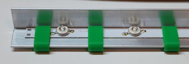

Aluminum LED PCB mounted on 3/4" x 3/4" aluminum L as a heatsink/mounting bracket/light guide, using printed ABS clips.  The clips hold the PCB tightly against the L to ensure efficient heat transfer.


One of the printed ABS PCB clips.  It snaps on tightly, ensuring heat transfer from the PCB to the L heatsink.


One of two 12 x 1W UV LED light bars that will be mounted vertically on the front of the printer.  The bright green objects are the brackets that snap into the t-slot frame of the printer.  The white LED bars will be mounted alongside the UV strips.

I found that the heatsink got pretty warm if I operated the LEDs at full power, so I dropped the voltage a bit and gave up just a little of the brightness in exchange for much cooler operation.  I set the buck converter for about 19.6V output and limited the current to 1.3A.  The voltage setting limits the current through the LEDs initially to just over 1A.  If the LEDs heat up because they are inside a warm printer enclosure, they'll try to suck more current from the buck converter, and when it reaches the set limit, the converter will operate in constant current mode and that will prevent thermal runaway.

Here's a short video of the printer putting down some fluorescent yellow filament with the lighting switched between the white and UV LEDs.

UMMD 3D Printer White and UV Lighting from Mark Rehorst on Vimeo.


Here's a still photo in which I tried to tweak the exposure to match what the eye sees when the UV lights are lighting up a fluorescent yellow print.  The photo just doesn't do it justice- in real life it's almost painful to look at the print because it glows so brightly.


Wednesday, August 2, 2017

UMMD 3D Printer Electronics

Update: The smoothieboard has been replaced by a Duet Ethernet board.  The information below is the original stuff.

Major components of the electronics in UMMD are:

In a 3D printer, the extruder requires the most operator input for maintenance and repairs.  The electronics comes in a close second.  Most people building coreXY printers put the electronics in the bottom of the printer, utilizing some of the "dead space" under the bed.  That can be convenient if the printer sits on a table, but UMMD is tall and stands on the floor, just like me.  Putting electronics in the bottom would mean getting down on the floor every time I had to access the electronics.  I also intended to use an LCD control panel to print from SD cards, and LCD panels generally don't work with long cable runs, so the LCD panel has to be kept close to the electronics.

I wanted to keep the electronics easily accessible, and outside of the heated enclosure, and I hate bending over, so I planned to put the electronics on top of the printer from the start.  Most of the electrical connections to the printer have to be made on the XY stage, so keeping the electronics close by keeps cable runs shorter.  The electronics are mounted on the left side of the top of the printer, under a plastic basket used as a protective cover (it's ugly- I'm working on it!).

There are two buck converters in the system.  One provides a source of 12V to power some fans and some of the white LEDs used to light up the printer.  The other is used strictly for powering the UV LEDs.  It would have been less complicated if I didn't have the 12V parts in the system, but it is easier to find 12V LED light bars, and I already had a couple 12V fans, so I used a buck converter.

The other buck converter is used to power the UV LEDs, something not absolutely necessary but aesthetically pleasing when printing fluorescent filament.

You can see more details about the LED lighting in UMMD here.

UMMD has three electrical fuses, one for the main power supply (which probably has its own internal fuse), one for the bed heater circuit, and a spare that is going to be used for an enclosure heater circuit, not yet installed.  Electrical fuses protect against fires caused by wiring or electronic failures.

The bed heater is powered via an SSR that is driven by the controller board.  When SSRs fail, they fail shorted - i.e. on.  The controller normally keeps the bed temperature regulated, but if the controller fails, or the SSR fails, the bed heater could get dangerously hot, and possibly cause a fire.  I added a thermal cutoff (TCO) to the bed plate to protect against that possibility.  It would actually be better to have the TCO mounted on the heater because the heater is attached to the bed plate with adhesive which could let go.  I will probably move the TCO to the heater itself by cementing it with high temperature silicone.  That way if the heater comes off the bed plate, the TCO can still do its job.  Details of the bed and support here.


TCO clamped to the rear edge of the bed plate.  Don't do this.  Mount the TCO on the heater using high temperature silicone.


I used a TCO with a operating temperature of 184°C.  That allows the bed to operate normally up to about 160°C (for printing high temperature materials) without opening the TCO.

The rest of the wiring to motors, etc., is standard stuff you can see in the Smoothieboard documentation.