Tuesday, July 23, 2024

Recapping a "New" Stereo Amplifier: a 25 YO Krell KAV-300i

 I recently bought a "new" stereo amplifier via ebay. It's a Krell KAV-300i made in 1999, based on date codes on output transistors and capacitors. Back when it came out it was often referred to as "the baby Krell". It looks and sounds like new. Like other Krell amplifiers, it's appearance is "brutal" - gray and black aluminum and steel, with lots of sharp edges to remind you that you should tread carefully when you walk by. 

Why would one buy an old amplifier instead of a new one? There can be many reasons- for some it's a nostalgia thing, maybe you like the way it looks, it can be a good way to save some money, assuming one has the ability to fix or maintain an old amp. 

Most audio amps, old and new, are class AB designs, including this Krell. The technology hasn't changed (though some more modern amps are class D). A new class AB amp really shouldn't perform any better than an old class AB amp. The main difference between class AB amps is the quality of construction, ease of service including availability of parts, and the circuits immediately before the amp stage -preamp/input switching.


The Krell KAV-300i front panel. Watch out for the sharp corners and edges! Very simple controls and no pots to wear out or get scratchy. There are buttons for power on/standby, input selection/mute, tape monitor, and volume up and down. LEDs indicate power on (blue, of course!), standby, selected input, tape monitor status, balance status, volume level, and mute status.


The rear panel, also very simple. There's a line fuse in the IEC line connector, and two power supply rail fuses, one at each speaker output terminal. There are connectors for a tape loop, these days mostly useful for adding tone controls of some sort, a preamp output that can be used to drive a subwoofer, and three inputs, the first of which can be balanced or unbalanced. Back in the day, balanced inputs were mostly used when the signal source had to be located far from the amplifier, but these days people are using them for short cable runs because they sound "better".

Also, like other Krell amplifiers, the inside is a real work of engineering art. There are only a few wires inside the chassis and all connections and components are clearly marked on the two metal layer, glass-epoxy, plated-through holes, PCB's silk screen layers. I believe this may be one of their last amplifiers that were built with through-hole components, making them particularly easy to service. Their newer stuff uses surface-mount parts.


First opening of the amplifier shortly after unpacking it. This is what you pay for when you buy Krell!  I wanted to look for anything damaged by heat or age. When I separated the power amp and preamp boards I found some heat damage. To my pleasant surprise, there was almost no dust inside or outside the amp. There are four circuit boards- one on the far left with the transformer input voltage taps, the front panel board you can't see, the preamp board on top in the back, and the main amplifier under the preamp board. You might be able to tell that two of the main power supply filter capacitors (4 black cylinders) are bulging slightly on the tops of the cans. There were no signs of anyone ever having worked on the amp.


The connections between the preamp board and the power amp board under it are made using header pins, not wires, so you can't mess up the connections unless you bend the pins which is easy to do, when putting the two boards back together. Be careful!

For contrast, here's the inside of my Soundcraftsmen PM860 amplifier that I bought new in the mid 80s. This is more typical of consumer audio stuff: a rat's nest of unlabeled wires and hard to reach circuits on unmarked PCBs- as awesome as it was/is, it was clearly designed to be inexpensive (really, how much does it cost to put a silk screen layer on a PCB?) and not designed to be serviced.


80's vintage PM860 amplifier- 205 W/ch at 8 Ohms, 400W at 4 Ohms, and 600W at 2 Ohms. Look at the mess of wires, placement of PCBs, etc. Not pretty. Think about how much harder it is to service this compared to the Krell amp.

What the Krell?!


The KAV300i, first manufactured in 1996, is an integrated amplifier, meaning it has input switching, volume control, and power amplifier in one box. Volume control is managed digitally using buttons on the front panel or remote control. There are a series of LEDs on the front panel that vaguely indicate the volume setting. You can also adjust balance by 6 dB or so, but only from the remote control. There are no tone controls of any kind.

This amp sold for $2300 in 1999. Adjusted for inflation, that's equivalent of $4,337.35 in 2024 dollars. If you buy a $4k amp today is it any better than the old Krell? Is it built as well as the Krell? Maybe, but you can get the Krell for a lot less than $4k, if you're willing and able to change the caps.

Owner's manual here.

Note: Krell's use of the "i" appended to the model name predates Apple's use on the iPod that came out in 2001 (and almost every other low-end piece of electronic junk since). An example of Krell's advanced technology? Oh wait, Krell appended the "i", and Apple prepended it. Such innovation! If Apple had appended instead of prepended they would have had the Podi, Padi, and Phonei (pronounced like phoney). Kudos to the folks at Apple for preventing that marketing disaster!

Input selection is done using relays that produce a gentle "click" each time they are activated, controlled from front panel buttons and the remote control. There are four inputs- one balanced (with the right cables and signal source - my TEAC VRDS-20 CD player for example), and three unbalanced. If you touch a selected input button a second time, the amp mutes. Touching the same input button again unmutes the amp. There is also a tape loop (people still used tape in 1999), and a preamp output that's mostly useful for driving a subwoofer.

The power switch doesn't fully cut power- it puts the amp in standby mode which draws about 50W from the power line even when the amp is "off". True audiophiles expect their electric bills to go up when they buy Krell amps! I calculate it will add about $60 per year to my electric bill. 

The power amplifier is an all-discrete transistor, direct coupled, class AB design with apparently high bias as the amp sits about 10F above room temperature even in standby (in standby the bias is reduced). As far as I can tell, standby mode just shuts off the inputs, mutes the output, reduces the output stage bias, and turns off the input and volume LEDs. Standby mode keeps the heatsinks warm so the amp is ready to deliver full specced performance from the moment it is switched fully on.

Blue LEDs first hit the market in the late 90s, and were initially expensive, so naturally, all high-end audio gear of that era had to use blue LED power-on indicators. This amp is one of those. As time passed and the price of blue LEDs came down, manufacturers of cheaper audio stuff started using them, too (to make people feel like they were buying a piece of high-end stuff?). 

Basic specs of this amp: 150W/ch at 8 Ohms, 300 W/ch at 4 Ohms, -3 dB frequency response from 0.6 Hz to 90 kHz. Weight: 10.9 kg (that's 24 lbs outside the civilized world). Note the wide bandwidth- that's unusual, even compared to modern amps.

Here's a review from Stereophile from 1996.  

Here's a review of the amp from 2009 (?).  

More here.  

And here.

When the amp arrived, I checked for DC on the speaker outputs and measured -7 mV on the left channel and -12 mV on the right, both easily within +/20mV spec. Of course I hooked it up and it played perfectly. I tested all the inputs and outputs, and all the controls and found no issues.


Recap or leave it be?


If you buy any electronics that is 20 or more years old, including speakers, it's always a good idea to consider replacing ALL the electrolytic capacitors. Electrolytic caps have a liquid electrolyte that slowly dries out causing the capacitance to drop and ESR to rise. As ESR rises, the cap runs warm, speeding up the drying process. If it gets warm enough, some of the remaining electrolyte vaporizes and pressure builds inside the capacitor. Eventually it can cause the cap to burst (that's why the cans have grooves stamped into the tops- they weaken the cans so that's where the caps will open), sometimes splattering whatever is left of the caustic electrolyte all over the circuit board or interior of the chassis. Depending on the circuit, degrading caps may or may not noticeably affect the sound quality produced, but eventually, those caps may burst or short and destroy other components that might be a lot harder and more expensive to replace.

I opened the amp up and found almost no dust inside, despite ventilation holes in the cover, and slightly bulging power supply filter capacitors. The bulging caps indicate that they are on their last legs and really should be replaced before any of them blows.


One of the old main power supply filter caps with the bulging top. I peeled the plastic cover off so it would be easier to see. The bulge indicates that the cap was running hot and building up pressure in the aluminum can. This is a ticking time bomb, waiting for the most inappropriate moment to blow.


Speaking of ventilation holes... The heatsinks for the output transistors are bolted to the steel bottom cover of the amp which has no ventilation holes. The top cover has some small ventilation slots located directly over the heatsinks. Hmmm. If I were building an amp with internal heatsinks, I would probably put ventilation holes directly above and below the heatsinks to get some convection to cool the amp. Apparently Krell didn't think it was necessary. Back to the recap...

It was clear that the main power supply filter caps needed replacement, but should I bother with the others? Hmmm. The circuit is direct coupled from input to output, meaning that there are no capacitors in the signal path. That's why the low frequency response goes all the way down to 0.6 Hz. The audio performance of direct coupled amplifiers tends to be stable over time because there aren't any slowly degrading caps in the signal path. There are a pair of 3300 uF electrolytic caps connected back to back to act as a nonpolarized cap in each power amplifier channel (to roll off low frequency response?- not sure). 

If I just replace the main power supply filter caps and put the whole thing back together, how long will the other 25 year old caps last, and will one of them short and kill some hard to replace semiconductors in the process, or leak and corrode a circuit board, and how long will it be before the amp has to be repaired? Caps are cheap, so I decided the sensible thing to do is to replace ALL the electrolytic caps. Then, maybe, I can count on another 25 years of trouble-free service. More on capacitor lifetime below...


Alrighty then, recap it is!


I'm no stranger to recapping jobs, having restored a bunch of antique radios, and bringing my M Audio computer speakers back to life, and recapping the crossovers in my speakers, so I dove right in. First, I found the service manual for the amplifier online, then proceeded to mark out all the electrolytic caps on the schematic, then verified their locations on the PCBs, and parts list. I also measured the physical size of each cap used to ensure that the replacements would fit.

The original capacitors were all made by Nichicon, a Japanese company that makes caps specifically for audio use. The data sheet says they use some special electrolyte for the audio specific caps, and audiophiles worship Nichicon, so I used Nichicon's latest, high performance, audio-specific caps- the UKW series, most of which are stocked by Mouser Electronics. The main power supply filter caps are from the LLS series because the UKWs don't come in 60V power supply filter cap sizes.

The original main filter caps, 6800 uF @ 80V, were 35 mm dia x 40 mm tall. I checked the dimensions of the amplifier case and found that I could install caps up to 56 mm tall, still leaving 3mm of clearance with the top cover, so I ordered 8200 uF caps that are 45mm tall to replace the 40 mm tall original caps. It's about a 20% increase in capacitance that may help the amp deliver even more solid low frequency performance than it did with the original caps.

Note- there's a LOT of empty space at the front of the chassis that could be crammed full of power supply filter caps if one really wanted to increase the energy storage. The amp specs and sounds good with the caps that are on the PCB, so I decided to just place new caps on the board.

Note: the amp has a NTC thermistor that functions as a soft-start device preventing huge current surge from the power line when power is first applied to the amp (by plugging it in). If you were going to modify the amp for much larger power supply energy storage you might need to change that part.

There are a bunch of 10 uF, 50V capacitors scattered around the amp, used mainly for low voltage power supply bypass at different ICs on the circuit boards. For those replacements I chose some super high reliability, low ESR Kemet caps that will probably outlast all the others. 

Electrolytic capacitor specs include projected lifetime based on maximum ripple current at rated voltage and maximum temperature (usually 85 or 105C). As the operating current, voltage, and temperature are usually less than the rated values, projected operating life increases. Here's a detailed article on estimating capacitor operating life. The simple rule of thumb to take from the analysis is that if you keep voltage  and ripple current less than rated values, for every 10C drop in temperature, you'll see a doubling of capacitor's rated lifetime. So a cap rated for 85C that is operating at 55C (like maybe in this amp that tends to run warm), should last 8x its rated lifetime. 

Lets assume you listen to music two hours per day, every day. The UKW Nichicon caps I selected are rated at 2k hours at 85C, so we can expect them to last 16k hours. That's 8000 days, or 22 years. The Kemet ESL caps are rated for 8k hours at 105C. They should last an astounding 256k hours, or 350 years (ya, sure, youbetcha!). Finally, the Nichicon LLS main filter caps are rated for 3k hours at 85C, so expect 32 years from them. Since it is unlikely that I'll be listening to music two hours per day, every day for the next 22 years, the amp should be fine even longer than that, and will outlive me. I will put a note inside the amp that it was recapped in 2024 so that the next owner will know whether they should recap it. Even though the projected lifetimes are measured in decades, I'd still replace electrolytic caps after 20-25 years (as I have done with this amp), even if they test good.

I ordered the new parts from Mouser for about $72 including taxes and shipping:


Oops! I ordered 2 sets of the 3300 uF caps and missed a couple others. Always double check your order!

Second order that included some parts I missed in the first order and others that I discovered needed replacing after I took the amp apart. This brings the total parts cost to about $100.


Recapping the Front Panel Board

Removing the front panel is pretty easy- first take the top cover off the amp- that's 12 x T-10 screws, then remove three more screws from the bottom front and the whole front panel and its PCB will be free to move.


Red circles indicate the screws to remove to free up the faceplate PCB once the whole faceplate is free. 


The front side of the faceplate board. Note- the LEDs all stand off the board and have to fit into holes in the front panel of the amp, so be careful not to bend any of them! The new caps will be soldered on this side of the board. They must have used one of the front panels as a soldering jig in the factory.


Faceplate board caps to be replaced, five total. 1x 1000 uF @ 50V, and 4x 10 uF @ 50V.

I replaced the caps, bolted faceplate back together and tested to make sure all the buttons, LEDs, and the remote control were working. No problems!


Recapping the Preamp Board


Next it was time to replace caps on the preamp board. There are some tight fitting parts at the back panel that fit between the preamp and power amp boards, so the best way to remove and replace the preamp board is to remove the back panel first. 


Removing the back panel to get to the preamp and power amp boards. Take out all of these plus 3x T-10 screws on the bottom. The binding posts will still be soldered to the output wires on the power amp board. There is no need to desolder them.


You have to remove these four screws to separate the preamp board from the power amp board. They go into 1.5" standoffs that set the spacing between the two PCBs to 38.1 mm.


Top of the preamp board with caps to be replaced circled. There are 5x 10uF @ 50V caps and 1x 47 uF @10V. Note- the parts list says the 47 uF cap (the black one in the photo above) is a tantalum type, but there was an electrolytic cap on the board. I replaced it with an electrolytic cap since that was what was in there.


These long header pins connect the preamp board to the power amp. They make it a little tricky to get the two boards back together because it is very hard to see them when you're attempting to mate them with the header sockets on the power amp board. 


Once the preamp board was recapped, I decided to move on to the power amp board without testing because getting the two boards back together is tricky. The pins and their sockets are between the two boards and it's really hard to see them when you're trying to put them back together. The trick is to get the two horizontal groups of pins aligned with their sockets first then carefully check the vertical row of pins before pushing the board down to seat it.


Recapping the Power Amp Board


There are twelve screws on the bottom of the amp that bolt the two heatsinks to the chassis. There are also two bolts that pass through the bridge rectifiers that hold the board down, and finally another screw that goes into a spacer near the back of the amp. I found it easiest to work by also removing the screws holding the line voltage selector board so it could move around a bit. I did, but you don't really need to disconnect the wires from the transformer to the power amp board.


These are where the screws that hold the power amp board down are located. There are also 6 screws in each heatsink holding them to the bottom of the chassis. I also circled the place where the power transformer wires attach to the board.


These are all the caps on the top side of the board that need to be replaced. At the top of the picture, you see the four main power supply filter caps- 6800 uF at 80V. I replaced them with 8200 uF @80V parts. That row of 10 pieces near the top of the photo are all 330 uF @ 100V. I replaced them with 470 uF @ 100V parts. The group of four at the center are all 3300 uF @ 16V wired as two nonpolar caps. I replaced those with same spec parts.


The circles near the corners are four more caps that need to be replaced- 47uF @100V. I replaced them with parts rated for 125C. The central area that is circled is a place where the PCB has been slightly toasted by some parts operating at high temperatures.


Close up of the toasted area of the board on the bottom side. The darkened area is centered on the two power transistors, so I suspect they are the primary source of heat.


This is the toasted area on the top side of the PCB. Note the discoloration and cracking in the surface of the two circled resistors. There are two transistors right below them in the photo. I suspect the transistors are running hot. Those resistors had to be replaced. 6.19 kOhm 1% 1W metal film type.


New caps, Zener diodes, transistors, resistors, and heatsinks in place. The transistors, resistors and Zeners are stood up off the board for better air circulation around them. Heatsinks are made from perforated aluminum as I was unable to find commercial parts that would fit in the available space. Note- some folks who saw this photo on the DIY audio forums commented that the solder joints didn't look very good- I went through and cleaned them up after this photo was made.


The seven relays that switch inputs, etc. are all one type: Zettler AZ847-5. They are specced for minimum operating life of 1x10^8 operations, so I don't think there are any concerns about them. The Zetttler parts are no longer made, but small signal switching relays are used in a lot of equipment, and there are equivalent parts available with essentially the same specs and pinout- one is the Panasonic TQ2-L-5V. They cost <$3 each.

Note: The DC rails have 12A fast-blow fuses for each channel. The fuses that were in the amp were 32V rated parts. The DC rails sit at 75V, so using 32V fuses isn't really a good idea. I replaced all four with 250V rated parts. Some golden ear out there is going to tell me that Krell selected the 32V fuses for their "sound". Hah!

I replaced all the parts, checked and adjusted bias, then DC offset per the instructions in the service manual, closed it back up, and it's all working and sounding great and hopefully will be for another 25 years. Woohoo!


Tuesday, July 16, 2024

Plant Stand

The finished plant stand. There's plenty of room for more plants!

For many years Ms. Kitty used to chew on any sort of plant I tried to grow, so I couldn't keep plants. A year ago I tried growing some basil and she didn't chew on it, so I tried a few others and sure enough, she left them, alone. 

Remember the stand I built for the sound bar? I have been using it for a plant stand ever since I mounted the TV on the wall and found a piece of old furniture to set the sound bar on. That stand was pretty narrow so it was a little risky keeping plants on it, and a little too low, and Ms. Kitty seemed to finally be done chewing on plants, so I decided to build a proper stand just for plants.


The sound bar stand that I cannibalized for the new plant stand.


One of the sound bar stand legs. It's all 1" iron pipe with printed TPU feet so it won't scratch the floor. I reused them for the plant stand.

I was at the Habitat For Humanity ReStore one day and saw that they had live-edge wood that was cut from local trees and kiln dried. I checked the size of the machines at the makerspace to make sure I'd get a piece of wood that would be easy to work with, then selected a piece of Honey Locust that was within the envelope of the makerspace machines. It was a little over 6' long and about 1 3/4" thick and about 17" wide at the widest point. It weighed about 50 lbs. It had a little twist and a little bow in it, so the first step was to flatten one side so it could be run through a planer.

We have a 5x8' CNC router at the makerspace, so I set the board down on it, with shims under the edges to stabilize it, then ran a 2" fly cutter over the entire surface to flatten it. Next I took it to a planer and put the milled side down and ran it through several times, shaving off just a little until the planer blades cut across the entire surface. Then I flipped it over and ran a couple passes on the other side.

Once it was flat, I used a table saw to trim off the ends. Now the whole board was flat, cut to length, and ready to finish.

Both sides of the board had really nice grain and I wasn't sure which side would end up as the top surface, so I finished all surfaces the same. I started by sanding with 80 grit, then 120, and finally 220. After sanding, I cleaned off the dust and applied Minwax Prestain Wood Conditioner, then applied two coats of Minwax oil based cherry stain. Finally I finished it with two coats of Minwax oil based Spar Urethane, chosen for its resistance to UV and water.


Finishing what would become the bottom side of the stand. This was at the literal center of the tree.


Finishing what would become the top side of the stand.


I wasn't sure which side would be the top surface- both sides had plusses and minuses- but the finish came out better on one side than the other so the decision was made. I stole the 1" iron pipe legs from the sound bar stand and added a couple tees and a 48" long brace. I screwed the pipe flanges at the tops of the legs directly to the wood top after drilling pilot holes for the screws.


Attaching the legs. The pipe flanges are screwed directly to the wood after drilling pilot holes. That #3 Phillips head bit in my Wera tool kit really came in handy- Honey Locust is very hard, dense wood!


I spent $125 for the Honey Locust board, about $35 for iron pipe fittings that I didn't already have, and another $40 or so for sanding discs for my orbital sander and the finishing supplies. The finished stand is 65" long, about 17" wide, and stands 29.5" high. I think it weighs about 70 lbs.


You can see the legs/feet a little better in this photo. It's all 1" iron gas pipe. One advantage of using threaded gas pipe is that all four feet can be adjusted to level the stand. The combo of the pipe and wood looks great in the old industrial building that I live in.


You can see the wood grain in the top surface here. It seems a shame to cover it with plants!


Happy plants! That's oregano on the left, aloe in the center, and basil on the right. Both the oregano and basil were started from $3 plants from Trader Joes. I like to use them for cooking and will probably grow a few more herbs now that I have space for them.


Friday, June 28, 2024

Another Recapping Project: Canton Ergo 22DC Speakers


Canton Ergo 22DC speakers and SVS 3000 Micro subwoofer.

Do you collect vintage audio gear? Or maybe you just have some stuff you've been using for years and it seems to work just fine. Over all the years you've been using that gear, the electrolytic caps have been slowly degrading, maybe doing the same to the sound, but so slowly you haven't noticed. If the gear is more than 20 years old, it's a good idea to replace all the electrolytic capacitors. Yes, even in speakers. Most speakers have at least one nonpolar electrolytic capacitor in the crossover. If you're not sure, open it up and take a look.

My brother recently gave me a pair of Canton Ergo 22DC speakers that look and sound great, but they are over 20 years old. I opened one of the speakers up and found two 12 uF and one 1000 uF nonpolar electrolytic caps. One of the 12 uF caps measured poorly on my LCR meter. I checked with Canton to see if I could buy replacements from them and the answer was a polite "no- they are no longer available". 

I did some searching and was unable to locate 12 and 1000 uF caps that matched the original part's 5% tolerance. However, I found 10% tolerance parts replacements at Madisound Speaker Components. The new parts are made by a company in Taiwan called MDL and are specifically for audio, whatever that entails. The original parts were rated for 23VAC (I know, weird, right?) and the new ones for 100V. It's OK to go up in voltage, but don't go down! They should last another 20 years.

I checked the new caps with an LCR meter and it showed the 12 uF caps to be 11.6 uF with ESR of  0.06 Ohms at 10 kHz, and the 1000 uF caps read about 991 uF at 100 Hz with <0.1 Ohm ESR, so all were within the 5% tolerance of the original parts.

If you're ever thinking about recapping an amplifier or other piece of gear, and not sure you have the skills, try recapping speakers first. It's pretty easy and hard to mess up!

If you can't find nonpolar capacitors that match the capacitance in your speaker, you can always make a non polar cap by connecting two polar electrolytic caps back to back. For example, if you need a 5 uF non polar cap and can't find one, get two 10 uF polarized caps and wire them like this:


You can connect the caps either way: + to + or - to -. The final value is 1/2 of each cap's value (use the same value for both!). Final voltage rating is the same as each cap's rating- if you use 50V caps, the nonpolar cap will be a 50V cap.


Surgery


In most speakers, you can get at the crossover by removing the bass driver. Just figure out how to take off the grilles without damaging the speaker cabinet's finish and you're half-way there. In the Cantons, the little logo badge at the bottom front pulls out revealing a spot where you can get your fingers under the perforated steel grille to lift it off the speaker.


The patient, prepped and ready for surgery.


Remove the logo badge and the grille.


Take out the woofer- Torx #15 tool required for this speaker.


The stuffing, removed from inside the speaker


The crossover board, held in place by the nuts on the screws that pass through the inductors.


The crossover out of the box- no need to disconnect either the drivers or the input terminals.

I used a desoldering pump and a soldering iron with a large tip to remove the old capacitors, inserted the new ones and soldered them down, and finally clipped off the leads. You don't have to worry about polarity with these caps!


The three new capacitors soldered in and ready to reassemble. Bolt the crossover back in place, replace the stuffing (very important!), screw the bass driver down, vacuum the fuzz off the front panel, and replace the grille.

The total time required, start to finish, was about 15 minutes for one speaker. The new caps cost about $15 per speaker. As long as the adhesives in the drivers hold out, and I don't do anything stupid with the amplifier driving them, they should last another 20 years.


Like Radiohead says, "Everything in its right place..."


Thursday, April 25, 2024

Mounting an MTB fender on a Wren inverted fork

Having recently retired, I have been thinking about things I want to do. I've been a bike geek for my entire life, and always wanted to try some long trips including off-road camping, etc., but never had time. Now I have time! I'm starting to have joint pain and other problems that will probably get worse over time, so I decided it's now or never.

I got a great deal on a new Priority 600X hard-tail "adventure" bike. It's an awesome machine that has a Gates belt drive instead of a chain, a Pinion 12 speed gearbox mounted at the bottom bracket, a Wren inverted suspension fork with 110 mm of travel, and Tektro Orion 4 piston hydraulic disc brakes.

When the 600X arrived I didn't have room for two bikes, so I sold my Priority Continuum Onyx. I was sad to see it go- it was a great bike! 

I'll make a thorough post about the 600X soon. 

I will be riding the 600X on Milwaukee's pot-holed streets as well as doing some off-road riding, so I wanted to fit it with fenders (aka mudguards) for wet weather riding. I did a lot of online shopping and review surfing and found the most promising ones to be made by MuckyNutz in the UK. I found a dealer on ebay and ordered a set. 

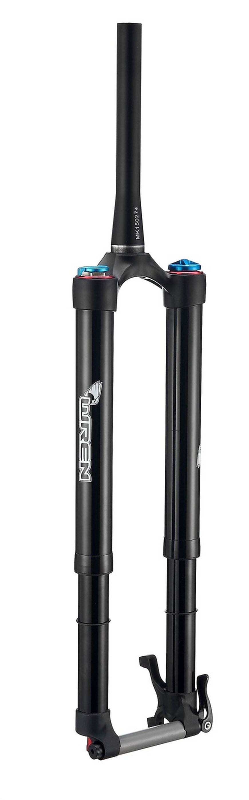
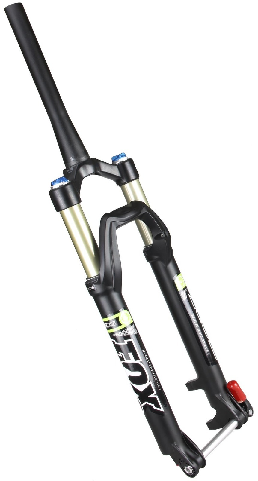
The rear fender fits on the bike just fine. The front fender was a little bit of a problem. MTB front fenders are made to attach to the fork lowers and bridge. The Wren fork is inverted - the lowers slide into the stanchions instead of sliding over them- so it doesn't have a bridge. There wasn't enough room to mount the fender on the lowers, so it has to go on the stanchions and the fender can't move with the wheel as the fork compresses. I tried mounting the fender on the stanchions but it wasn't stable enough- it really needs a bridge to stabilize it. 

The Wren "inverted" fork. The "lowers" slide into the stanchions and there is no bridge.


Typical MTB fork. The "lowers" have a bridge connecting them together and they slide over the stanchions. The bridge is a convenient place to mount a fender, light, etc. 


Almost every problem, both personal and scientific, can be solved with a 3D printer, including this one. I spent a few minutes measuring the fork and the fender and designed a 3D printable bridge. It fits the stanchions tightly without requiring any additional clamps. I printed it with TPU and tried it out. Perfect!


The fender attached to the fork stanchions with velcro tape. It was very wobbly.  The slots in the top of the fender are for using velcro tape to stabilize the fender on this fork's nonexistent bridge.


The fender mounted with the 3D printed bridge. Very stable! The fender can be installed and removed in just a couple minutes without tools.


The 3D printed bridge. I used black TPU filament. It fits the stanchions tightly and stays put without any additional clamps or tape.

The fender is mounted on the stanchions that do not move with the wheel when the fork compresses. That means it has to be mounted pretty far above the wheel so the wheel won't hit it when the fork compresses, or for street riding, mount it close to the wheel and lock out the suspension. There's plenty of room along the stanchions for either use.

If you have a Wren fork and want to add fenders, you can download the STL file for the bridge here.

Monday, April 1, 2024

Fun for Cats!

 Arrakis 2.0 has been my coffee table for well over a year. I probably turn it on a couple times a week to just change the pattern currently on the table, or to draw new patterns. When the 1000 mm/sec spiral erase pattern runs, Ms. Kitty recognizes the sound that the table makes and comes running to chase the ball. She will push anything on the table to the floor so it won't be in her way. 

I'm hoping to catch that on video one day and will post a link here if I do. There's another thing I want to catch on video. Sometimes she spins around so fast that she loses her footing (maybe she gets dizzy?) and falls off the table. If I catch that on video, Ms. Kitty and I will be making the late night talk-show tour and probably die rich and famous.

Anyway, I was thinking about cat toys and which ones keep Ms. Kitty interested and which ones she gets bored with. I've come to the conclusion that cat toys that will hold the her interest for a long time should have random motion at speeds that she can keep up with or a little faster. The toys Ms. Kitty never seems to tire of are balls hanging by string on the end of a stick and a laser pointer. Both exhibit movement that will catch a cat's attention and move as fast as you move your arm. Everything else bores her to tears.

That got me thinking that she might find it interesting if I make the ball on the sand table move in random directions at random speeds. To that end I wrote a spreadsheet that would generate the necessary gcode. The spreadsheet generates gcode that will move the ball a random amount at a random speed, then stop for a random period before darting away.

The spreadsheet needs to know the size of the table (or the area to which you want to restrict the ball's motion), the minimum and maximum allowable speeds, and minimum and maximum allowable dwell time. It's currently set up to create 500 moves, so if you average 2 seconds of dwell time at each point, you can expect the pattern to run for about 17 minutes. That's long enough for Ms. Kitty to lose interest (she's usually good for just a few minutes), but can be easily extended if she ever demonstrates interest for the duration of the pattern. 


Now I know what you're thinking. "I'd like to try this with my cat and sand table." There's a link to the spreadsheet, below, but before you get too excited, you should know that I run the ball between 500 and 1500 mm/sec with acceleration at 10,000. Ms. Kitty won't pay much attention to anything slower. Arrakis 2.0 achieves that speed by using servomotors instead of steppers. If your table uses stepper motors, it's probably limited to a maximum speed around 100 mm/sec, and that might not draw much interest from your cats.

The servo motors are NEMA17 size, so you might be able to fit them into your sand table, but they also need step/direction/enable signals to run, and a beefy power supply- Arrakis 2.0 uses a 350W 24V supply.

Here's the spreadsheet.

I tried to implement similar random motion using arcs instead of straight lines, but it's a much more complex problem- the arcs can go beyond the limits of the table and that causes the table to stop moving. If I make any progress on it I'll post it.

Wednesday, March 13, 2024

Disco Shroom!

 A friend gave me a mirrored mushroom that threw many light beams when hit by the morning sun streaming through my east window. Nothing exceeds like excess, so I looked around and found a small, 4 rpm turntable powered by a USB dongle. I didn't want any wires for Ms. Kitty to chew on, so I also ordered a couple 5V solar cells to connect to it with the shortest possible cable. 


The Disco Shroom. Pen for scale (I didn't have a banana...)

I designed a base to hold both the solar cell and the turntable with wires hidden so Ms. Kitty can't chew on them. You can see it all below.


CAD render of the base for the disco shroom. The solar cell is mounted at about 45 degrees and wires feed through the tunnel that connects the hollows in the print. The whole thing sits 75mm above the window sill so the window frame doesn't cast a shadow on either the solar cell or the disco shroom.


Printing the base on UMMD. I printed with 1 mm nozzle, 2 mm walls, and 15% triangle infill. It took about 18 hours to finish the print and used 1200 g of PETG filament.


The finished print.


Wires stripped, twisted, and soldered to the solar cell. I put some hot melt glue over the solder points to protect them- probably not necessary.


Double sided foam tape (red) used to hold the solar cell in place.


Wires are fed through the tunnel to the turntable mounting position.


The Turntable opened. The table (right) is mounted using a single screw through the center.


Be careful when you open up the turntable. There are five little wheels/bearings that can fall out of the base and get lost if you're not paying attention.


This is probably the most expensive part in the turntable- a 6003RS bearing!


Cut the battery leads from the terminals, strip, and solder them to the solar cell leads. I put heat shrink tubing on them to prevent shorts and used a screw to hold the wires down inside the base.


Underside of the turntable base. I threw away the battery cover and ran the wires from the solar cell into the turntable base through the battery cover latch hole.


Completed assembly, ready to go on the window sill.


Another view of the completed assembly.


Yet another view of the completed assembly.


Thursday, September 7, 2023

A few updates to Arrakis 2.0

Arrakis 2.0 recently developed a minor problem- the ball started shifting while it was drawing patterns and it started making unusual noises. When I opened it up I found that the pulley on the left side motor had come loose, but wasn't completely rotating on the motor shaft. It would rotate a little with some reversals of direction, galling the motor shaft in the process. 

I had used some locktite on the set screws for the pulley and couldn't get them to tighten, and could barely get them loose enough to get the pulley off the motor shaft. I installed a new pulley which quieted the mechanism back down and I decided to address a couple things I had been thinking about for a while.

The homing sensors were mounted high on the motor mounts and were easy to break if I was taking the table apart to transport it. I wanted to redesign that part of the mechanism so they sensors and flags could be positioned where they would be less likely to get broken.

There were three parts that needed redesign/print. The magnet carriage, the left side Y axis bearing/pulley block, and right motor mount. 

Magnet carriage

The original magnet carriage design had a flag on the top piece which is why the X axis home position sensor was mounted in a precarious position on the right side motor mount. I wanted the sensor to be mounted lower, so I had to redesign the magnet carriage to put the flag on the bottom piece instead of the top piece. I also wanted to make the X home position somewhat adjustable and decided it would be easier to adjust the flag than to adjust the sensor position, so the flag is now a piece of plastic that attaches to the magnet carriage with a screw. The new magnet carriage consists of the old bottom piece that has become the top piece, and a newly designed and printed bottom piece that includes a tab to mount the homing flag.


Original magnet carriage. The projection to the left is the flag for the X axis homing sensor.


The new magnet carriage design. The old bottom piece has become the top piece and the flag (black) mounts with a screw so it can be repositioned if needed. 


Right side motor mount

Now that the flag was moved lower, the sensor could be mounted lower, so the newly designed motor mount includes an extra wall to mount the X axis homing sensor. I mounted the sensor using some industrial double-sided tape. If the adhesive lets go, I'll drill some holes and screw the sensor to its mount.


The original right side motor and mount with the dangerously positioned X axis homing sensor.


The new right side motor mount with the X axis homing sensor moved to a much safer position.


Left side Y axis bearing/pulley block

The original design had the Y homing flag glued to the top of the pulley block and the sensor on the top of the left side motor mount, both in easily bumped positions. The new design has the flag printed as part of the bottom piece of the pulley block, and the sensor mounts on the side of the motor using the same tape I used for the X axis sensor.


The original left side Y axis bearing/pulley block with the Y axis homing flag glued to the top of the block.


The new left side Y axis bearing/pulley block with the homing flag printed as part of the bottom piece.


The original left side motor with the Y axis homing sensor mounted on top of the motor mount where it could be easily broken.


The new position for the Y axis homing sensor on the left side motor. It is taped to the motor using some double sided adhesive tape.


Now everything is secure and in positions that are not likely to get bumped when taking the table apart or putting it back together.