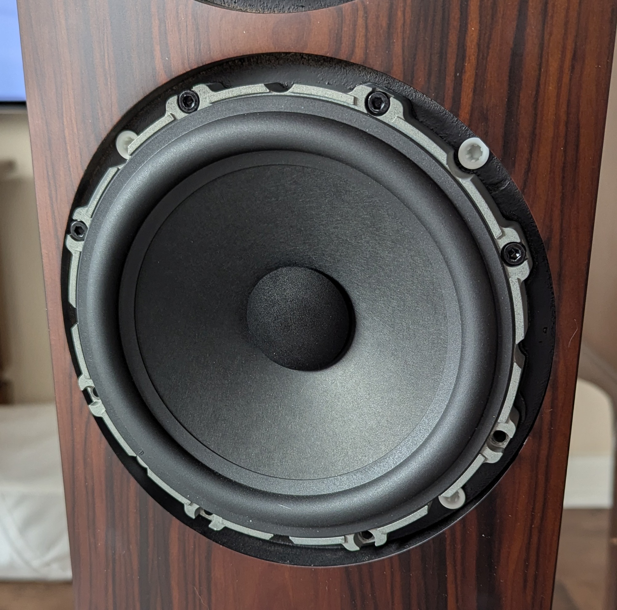
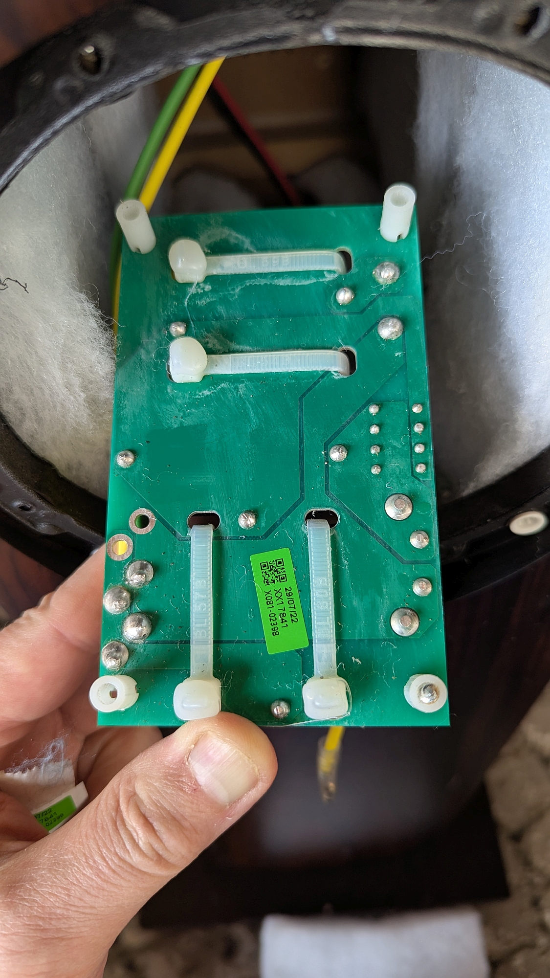
Update: I designed, built, and used an improved diaphragm stretcher that works better than the one in this post. You can see details here.
Now back to the original post:
I recently prepared a very long post on my efforts to restore a pair of Quad ESL-63 electrostatic loudspeakers made in 1983. That post was made almost daily as I did the work, and includes a lot of things I tried that didn't work. This post leaves out the stuff that didn't work and summarizes the stuff that did. I have omitted a lot of detail here, so check the other post if anything isn't clear.
Main parts of the rebuild:
1) remove tapes and their adhesive residues that were used in the assembly and replace them
2) Reglue stators
3) Replace diaphragms
4) Replace dust covers
5) Repair Electronics
It's best to do this work in a room that's free of dust, dirt, and pet hair. Keep a vacuum cleaner handy and stop to vacuum things off at each step in the process. It doesn't take much dirt to cause the drivers to hiss and whine.
I used lint free microfiber cloths whenever I wiped anything with either a solvent or water. Paper towels might leave lint behind that could turn into a source of noise.
I wore 5x and 2.5x loupes when doing detailed work- being able to see what you're doing is really helpful. Use plenty of light in the room, too!
The Tapes
For some reason these speakers had a bunch of different foam and other tapes used in their construction. After 40 years, some of the adhesive became brittle and the tape wasn't sticking well, and foam tapes were rotting away, usually leaving sticky residue behind.
Removing the old tape typically involved peeling it off, then scraping as much of the adhesive residue off as possible. Finally, solvents were used to remove the last of the residue. I used Goo Gone, an orange oil based solvent, and Goof Off, a very volatile solvent.
The purpose of some of the tapes used was questionable, but I replaced almost all of them anyway.
Note: some folks may get the idea that they can use double stick tape to mount the diaphragms on the driver grids. No, you can't. It doesn't work. The problem is that the tension on the film will pull the adhesive from the tape inward, toward the center of the speaker, more importantly, the tension on the diaphragm will be reduced when it does. That will lower resonance and may cause the diaphragm to stick to one of the stators whenever power is switched on.
Here are all the locations of the tapes that need to be replaced. A, C, and D are all inside the dust covers, so it's absolutely critical to clean the old stuff out and replace it with long lasting materials. Double sided tapes are used to mount the steel grids on the speakers and to mount the dust cover film. All others have adhesive on one side only.
Adhesive tapes for 2 speakers
location
total length
width
thickness
adhesive
type
A
driver mounting brackets
48"
3/8"
1/4"
single
foam
B
vertical frame supports
248"
3/8"
1/4"
single
foam
C
driver mounting brackets
120"
1/2-3/4"
3/4"
single
foam
D
top and bottom dust cover mounts
184"
3/8"
1/4"
single
foam
E
inside bottom panel
8"
3/8"
1/4"
single
foam
F
top and bottom of frame, holds grids
200"
5/16"
1/8"
double side
foam
G
top and bottom of frame, over grids
234"
1/2"
single
gaffer
H
vertical edges of grids
256"
1"
single
gaffer
J
dust cover frames
448"
3/4"
1/8"
double side
foam/other
Note: F tape seems redundant- the G gaffer tape wraps around the driver enclosure, preventing the grids from moving. Maybe I'll use some of the same tape used at B and D to prevent the grids from rattling...
I used EPDM rubber weather seal foam tape that should hopefully last longer than the original polyurethane foam tapes that the factory used. For the dust covers I used 3M VHB double stick tape. I didn't use double stick foam tape at the top and bottom edges of the metal grids, and I didn't apply gaffers tape around the top and bottom of the driver enclosure. I want it to be easy to go back in and fix things if it becomes necessary. If they're still working right in 6 months, maybe I'll put the tape around the top and bottom edges of the driver enclosures.
The Stators
Each speaker has four drivers. Each driver is made of two plastic grids that clamp together, one at the front side and one at the back side of the speaker. The front side grid has the diaphragm glued to it and the back side grid has conductive metal strips that contact the diaphragm. Both grids have stators glued to them. The back side stator has some fine nylon (?) cloth glued to it to dampen the resonance of the diaphragm.
The stators are thin, perforated PCB material that has copper on one side, covered with some sort of clear coating. The diaphragm sits about 2.5 mm away from the stators. When the stator glue bonds fail, the stators tend to curl inward toward the diaphragm, resulting in contact that makes noise even when the speaker isn't playing music, due to the 5.25 kV bias.
Once the stators start to let go, they need to be removed completely and reglued. If the stator glue bonds fail on the front side grid, the diaphragm has to be removed to reglue the stator, and then the diaphragm has to be replaced.
Usually, some of the stator glue bonds will have failed, so you break the stator free of the grid by pushing on the stator where the bonds are already broken and keep pushing until all the bonds are broken. You'll need to unsolder the electrical connection clips to remove the stator completely, and then clean flux off the solder pads using IPA.
Here's how you find broken stator glue bonds:
Original solder on one of the center drivers. Do you think they used enough solder? The black stuff on the edge is where one of the metal clips that hold the two sides of the driver together was positioned. All those clips had a little rust on them.
Aluminum clamped to the stator for desoldering. You have to remove the solder so the stator will sit down flat in the grid. The aluminum acts as a heatsink to protect the cloth that's glued to the bottom of the stator (back side stators, only).
Stator with flux from desoldering wick. That needs to be cleaned up.
This is what it should look like after you clean the flux off by wiping with a towel soaked in IPA.
Scraping the stator glue off one of the grids:
I also used the scraper to gently remove any excess glue from the stator. Don't get too aggressive- you don't want to cut into the plastic coating that covers the copper on the stator.
Once the grid and stator have been scraped and are ready to glue, vacuum them off to get rid of the glue dust. You don't want any foreign objects to get into the drivers or they will make noise.
This is the glue I used for the stators. One bottle is plenty to reglue all the stators for two speakers.
I applied the glue using a 5 ml syringe with an 18 gauge gluing needle. The syringe can be reused, but you'll need a new needle for each stator you glue, so buy a bunch of them. They're cheap.
Applying glue to the grid. I use clear polyurethane Gorilla Glue and wipe the grid with a cloth dampened with distilled water just prior to applying the glue. Then I wipe the stator with water before setting it down on the grid/glue. The glue needs the water to set properly, so don't skip this step. Glue only goes on the vertical ribs of the grid. It took me about 10 minutes to apply glue to all the ribs on one grid.
This is the stator clamping tool I made. The 1" thick foam strips are mounted on a piece of plywood about the same size as the driver. When gluing a stator, a couple kg of weight is placed on the plywood to ensure the entire stator is pressed against the grid.
This is how the clamping tool sits on the stator and grid. When you are actually gluing a stator, put a layer of saran wrap down before you put the clamping tool on the grid/stator. You don't want excess glue to stick to the foam.
I dampened and applied glue to the vertical ribs on the grid, placed the stator, covered with saran wrap, then placed the clamping tool and some weight on it to hold the stator flat against the grid.
The Diaphragms
The diaphragms are very thin (3 um) polyester film (Mylar is one of many brand names) stretched tight on a rigid frame, and they have resonances like a drum. I tested the factory diaphragms before I pulled them off their grids and found a consistent 86 Hz primary resonance. The test was performed by tilting the driver up vertically, then "thumping" the diaphragm close to its center, using a steel ball hanging from a thread. I placed a UMIK-1 measurement mic within 1 cm of the diaphragm and ran Room Equalization Wizard (REW) software on a laptop. I used the Real Time Analyzer (RTA) in REW to plot the spectrum of the sound captured by the mic. I used the same test method to tune the replacement diaphragms.
One of the drivers opened up. The piece on top is the back side driver grid, the bottom is the front side grid with the diaphragm attached. The gray stuff is the high resistivity coating on the diaphragm. No, it's not dirty, it's supposed to look like that. The metal tape at the edges of the top part makes contact with the coating on the diaphragm and allows charge to transfer to the diaphragm. You can see a thin cloth covering the stator. That's there to dampen diaphragm resonance. Don't remove it, and try not to damage it. Be careful when unsoldering the electrical connections to the stators.
Diaphragm coming loose in a driver. The problem is that the glue the factory used doesn't bond to the polyester film. This diaphragm has to be replaced, even if the driver plays OK.
This video shows how little effort it takes to peel the factory diaphragm off the grid. The glue they used didn't bond to the film.
I used a pneumatic stretcher to put tension on film and tuned the resonance to match the factory diaphragm resonance, before gluing it to a driver grid. The stretcher is a table with a hole in the center that matches the size of the driver grid, and has a wood lip. I put double stick tape on the lip on the underside of the table, neoprene foam on the top side of the table, and a bicycle tire tube is stretched over the lip of the table. The table is built so that it can tilt up for resonance testing/tuning while a diaphragm is being stretched.
Tilting stretcher table to allow easy and safe resonance testing of the diaphragm before gluing it to the driver grid.
The original diaphragms were a multilayer mystery, but comments by the engineer who designed the speakers indicate that they used a 3.5 um thick polyester film, and then applied multiple coatings to make the diaphragm slightly conductive, a necessary condition to apply charge to the diaphragm and have low distortion at large excursions (usually low frequency signals). I was unable to locate 3.5 um film, so I used 3 um film I was able to buy via ebay.
Replacing the diaphragms is a multistep process.
1) Remove the old diaphragm and glue that held them on their grids. I used a scraper and a solvent called Goof Off to remove the glue.
2) Lay the film on the top of the stretcher table, start at one edge and pull the wrinkles out of the film and stick it to the tape on the lip of the table. Then go to the opposite side of the table and do the same, then do the same at the other two edges.
Back in the 80s an engineer from 3M recommended 4693H contact cement for gluing the diaphragms and he was absolutely right about it. The stuff bonds to both the diaphragms (they way the original glued didn't) and to the grids. I used a silicone squeegee that I cut down to about 15 mm wide to spread the glue on the diaphragms and the grids.
How well does 4693H bond to the diaphragm? Here's me trying to peel off some film:
Rolling the film out on the stretcher table- film is stuck to the stretcher on the right end of the table to keep it from flying around. Note- my stretcher requires a significant margin of film around the driver to allow the film to attach to the stretcher. Be sure you order enough of the film!. I went through an entire 20m roll of film to replace the diaphragms on 8 drivers (two speakers).
This is what the diaphragm looks like on the stretcher before it gets stretched. Don't worry about the wrinkles, they will disappear as soon as the tube is inflated. The black stuff is neoprene foam that lets the slightly concave grid perimeter contact the glue everywhere.
3) Once the film is stuck to the table, I tilt it up vertically to inspect it and make sure the film is stuck down on the tape everywhere and make adjustments as needed. Once it looks good, I connect a tire pump and put a few strokes of air into the tube. That takes out all the wrinkles as it puts the film under tension.
This is what the film looks like on the underside of the stretcher before the tube is inflated. This is when you want to make any adjustments to the film position, before inflating the tube and tensioning the film.
The diaphragm thumper- just a ball bearing glued to a piece of thread. Simple but VERY effective!
The tight diaphragm being tested for resonance. The mic and thumper are positioned as close to the center of the diaphragm as possible. I made a couple 3D printed clamps and a short "boom" for the thumper. The RTA in REW displays the spectrum of the sound that the mic picks up.
The tight diaphragm glued to the grid (and stretched on the table) behaves like a drum and has a primary resonance and multiple other resonances based on the dimensions of the driver. The diaphragms that came from the factory had a consistent primary resonance of 86 Hz.
This is what the resonance typically looks like in the REW RTA. The primary resonance is the highest peak at the lowest frequency due to the longest dimension (the width) of the driver. The lower peaks at higher frequencies are due to the shorter height of the driver and maybe interactions/interference between the waves moving on the film. I set resonances of the new diaphragms slightly higher than the factory numbers, assuming that over 40 years the factory diaphragms may have "relaxed" a bit, and to allow for the extra mass that will be added by the conductive coating.
4) Tune the resonance of the film on the stretcher by pumping more air into the tube (or letting some air out, though I never had to do that). Once you have the resonance where you want it, disconnect the the air pump to prevent slow leaks through the hose or pump. Apply 4693H contact cement to both the grid and the film on the stretcher. I spread the glue with a silicone squeegee that I cut down to about 15 mm wide. Try to keep the glue on the film in the area of the neoprene foam. Let the two pieces sit for 20 minutes to allow the glue to set.
5) Once the glue is set, tilt up the stretcher and check the resonance one more time. Adjust the air pressure as needed, then carefully set the grid down on the tight film on the stretcher. The film and grid will bond instantly, so be very careful! I manually pressed the edges of the grid down on the film then put some weight on top of it and let it sit for a couple hours.
6) When you're ready to free the grid from the stretcher, let some air out of the tube and slice the film close to the tube, leaving a wide margin of film around the grid. Lift the grid up and turn it over to inspect it- there should be absolutely no wrinkles anywhere. If there are, you'll have to do it all again.
Grid stuck to the diaphragm on the stretcher.
After releasing air pressure, cut the grid free by cutting the film all around the grid near the tube, leaving excess film attached to the grid.
The wrinkle free diaphragm on the grid is ready to have the excess film trimmed off. Pull gently on the film and slice it away from the edge of the grid with the razor knife blade pressed against the edge of the grid, using it as a guide.
7) Now carefully use a fresh, sharp razor knife to trim the excess film from around the driver grid.
8) The next step is to make holes in the film around the the three center posts where screws pass through the driver. I use a soldering iron with a small tip and temperature set to 265C. Hold the soldering iron with one hand and use your other hand to steady it. Put the tip down on the film right next to the post and use the plastic post as a guide and just move the soldering tip around the post, keeping it in contact until you've made a complete circle around the post. Remove the soldering iron by lifting it straight up. Next do the same at the other two posts. Finally, use some tweezers to remove any hairs or discs of film that remain stuck to the posts.
Small tip on the soldering iron.
This is what the holes in the diaphragm should look like after removing film disc and any hairs that are produced. Use your other hand to steady the hand holding the soldering iron, and use the post as the guide for moving the soldering iron.
9) Now you can check the resonance of the diaphragm, you just installed. Tilt the driver up vertically and adjust the mic and thumper positions as close to the center of the diaphragm as possible. Thump the diaphragm and read the resonance in REW.
Checking resonance of a diaphragm after gluing it to the grid and making holes for the center screws.
In my setup, the driver resonances come out about 10Hz higher than the resonances I measure on the stretcher. I think this is because the open area in the stretcher is a little larger than the open area of the driver grid. When I stretch film I set the resonance on the stretcher about 10 Hz below the target resonance.
10) Apply the high resistivity coating to the diaphragm. The coating doesn't cover the entire diaphragm- some specific areas have to be masked off. I 3D printed a set of masks to make this job very easy.
This is the area (gray) of the diaphragm that needs to be coated. The left and right edges are left uncoated to reduce leakage current due to proximity with the metal frame that the drivers are mounted on. The center circles also need to be blocked out because of the metal screws that go through the holes.
Driver with masks and blue masking tape on long sides, just after spraying with Licron Crystal.
The masks are made based on the uncoated areas of the original factory diaphragms. The coating process is easy- put masking tape on the long sides of the driver grid, place the masks on the ends and on the center holes, shake up the can of Licron Crystal and spray. I spray in two passes, right to left, then left to right, then turn the whole grid 180 degrees and do two more passes. Then I take the masks off and set the grid on a shelf for a few hours to dry.
End mask to block conductive coating on new diaphragms. Dimensions in mm. If you make holes in the specified locations you can use screws to align the mask with the driver, otherwise, just put some masking tape on the edges to hold it in place while you spray with Licron.
One of the hole masks showing the M3 screw that fits into the holes in the grid supporting the diaphragm and ensures proper positioning when applying the Licron.
11) After the the Licron coating has dried, I test it with a resistivity meter to see that the coating is very weakly conductive.
Checking the resistivity of the coating, in this case 10^9 Ohms/square- great! The coating process is so reliable, I would consider the resistivity meter optional.
12) Once the diaphragms are all coated, reassemble the drivers by installing the metal clips at the edges and the 3 central screws and nuts. Then you can mount them in the speaker again and reconnect all the wires you unsoldered.
The Dust Covers
Some people claim the speakers sound better without the dust covers. Some go so far as to remove the socks, metal grids, and the dust covers, exposing the drivers to everything floating around in the air including dust, pollen, pet hair, and bugs, and running the risk of electric shock to anyone foolish enough to touch the drivers while the speakers are operating. I don't recommend operating without all those things in place.
There are two dust covers in each speaker, one each at the front and back of the driver enclosure. The dust cover frames snap onto the aluminum side pieces and a couple plastic pieces at the top and bottom of the driver enclosure. The frame is barely rigid enough to support itself when it isn't snapped onto the speaker. The dust cover is made from the same film that's used for the diaphragms, and like the diaphragms, it should be wrinkle free. The only way to achieve that is to put the film under some tension, then attach the frame pieces to it, then mount it in the speaker and use a heat gun to shrink the film and take out the wrinkles that will inevitably appear. This is by far the worst part of the design of these speakers.
Start by marking out the outline of the dust cover frame on the work surface using masking tape. Make sure you get it square by measuring diagonals! The inside edges of the tape are where the outside edges of the frame pieces will be placed.
Applying the VHB tape to the frame pieces. The tape is wide enough to cover two pieces at a time, so I stick it to the two pieces laying side by side, then cut them apart with a razor knife.
The frame pieces cut apart.
Roll out the film and tape opposite corners to the table, pulling and applying tension as you go.
Next tape opposite sides, pulling and applying tension as you go.
Now add more tape on opposite sides, pulling and applying tension as you go.
Place the metal bits into the ends of one short side of the frame, and peel the backing off the VHB tape. Use the edge of the frame piece and the two metal bits to align the piece with the tape on the table top, and stick it down- be careful not to let it touch in any wrong spot as the tape will not let go of the film!
First frame piece stuck down on the film. Now take the metal bits out of the ends and put them on one of the long frame pieces...
Note the orientation of the metal piece- they can fit two ways, but only one is correct! Peel a couple cm of the backing tape off.
Hook the metal piece into the short frame piece that's already stuck down, and start sticking the long frame piece down, peeling the backing away as you go. I flexed the frame piece a little to set the center of it about 1mm inside the blue tape outline- this will help tension the film when the frame gets installed in the speaker. Now stick down the other long frame piece following the same steps.
Second long frame piece stuck down. Now prep the other short frame piece...
Put the metal piece on the end of the short frame piece, peel some of the backing off the tape, and get the frame piece into position- don't set it down yet!
Holding the frame piece up, peel off the rest of the tape backing. Keep the center elevated so it doesn't stick to the film and then bring the end down and hook the metal piece into the long frame piece, and finally let the short frame piece down to stick to the film. The hard part is over!
Now cut the frame free of the film that's taped to the table using a fresh razor knife held at a very low angle.
Frame cut free of the film on the table. There are going to be wrinkles- don't worry about it. Take it to the speaker, slide it into position, and snap the frame down onto the mounts in the speaker. There will be wrinkles- don't worry about it! Start working on the wrinkles with a heat gun- use a low temperature setting and keep the thing moving- you don't want to burn a hole in the film!
Dust cover on the speaker. Notice how smooth the reflection looks in the surface of the dust cover!. But there are a few small wrinkles at two corners...
Small wrinkles in one corner that could not be removed with the heat gun.
Small wrinkles in another corner that couldn't be removed with the heat gun. The other two corners were wrinkle free.
That's it! Heat shrunk film relaxes over time, and eventually, wrinkles may reappear in the film. Also, the adhesive on the tape remains soft. Tension on the film will pull the adhesive toward the center of the dust cover, also releasing tension - this is why you don't use tape to hold the driver diaphragms! The ideal attachment would be to use the 4693H adhesive I used on the driver diaphragms- it will not move under tension.
When and if I get around to rebuilding these as 989s, I will design the dust covers to have rigid frames that will be much easier to install.
The Electronics
The schematic of the speakers changed a bit during the early years of manufacture, so your speakers may be a little different from mine. In my case, the electronics was all working fine so the only thing I had to do was replace the nonpolar electrolytic caps at the inputs of the speakers (based on their age, not performance). I ordered new 220 uF NP electrolytics and some 4.7 uF PP film caps to bypass them. I also replaced a 1000 uF 16V cap used in a power supply for the protection circuit in each speaker. This schematic appears to match my speakers, though the speaker were made in 1983 and the schematic is dated 1989.
An ESL-63 schematic from 1989. Earlier versions might be a little different. The red box is the input circuit, the green box is a HV clamp, the pink box has the delay line, the orange box has the LPF for the bass panels, the blue box is the HV bias circuit, and the yellow box is the arc prevention circuit.
A lot of the circuit is there to protect the speakers from misuse. Looking at the input circuit in the red box, there's a MOV (a type of self resettable fuse) that protects the audio transformers from too much current in the primary windings. You'll see the 220 uF cap in parallel with a 1.5 Ohm resistor connected to the low voltage side of the audio transformers. The transformers step up the voltage from the amplifier to a few kV (hence the warning stickers on the transformers). You'll also notice a triac that, when switched on, shorts out the primary side of the input transformers (and puts the 220 uF cap and 1.5 Ohm resistor across the amplifier output! That's probably the only condition when the MOV would open up, protecting both the amplifier - we hope - and the speaker from the large currents that would flow were the MOV not there).
That triac is driven by the arc preventer circuit (yellow box) which detects the ionization of the air that occurs just before an arc forms. So if the speaker is being badly overdriven, and the air starts to break down, the arc preventer will turn on the triac as described in the above paragraph. This only works if the speaker is powered on!
The blue box is the voltage multiplier that provides the 5.25 kVDC bias to the speakers. It's a standard Cockcroft-Walton voltage multiplier that charges the caps in parallel and discharges them in series. There's a small neon lamp and capacitor connected to the output as well as a 10 Mega Ohm resistor. The resistor limits current available to charge the diaphragms and helps keep them operating in constant charge mode for low distortion. The neon lamp only lights up and conducts when the voltage across it is about 90V. That happens at power up when there's little charge left on the diaphragms, and if the charge leaks away from the diaphragms indicating that there is some dirt or foreign object (like a dead bug or pet hair) trapped in the speaker between the diaphragm and the stator or frame of the speaker. There will always be a little charge leaking away from the diaphragms into the air, so the neon lamp will flash occasionally in a normally functioning speaker. The frequency of the neon lamp flashing is a good indicator of the condition of the speaker. That lamp should only flash briefly once a minute or so. Frequent flashing indicates that it would be a good idea to inspect the speaker and maybe do some cleaning. The neon lamp is inside the electronics enclosure where you can't see it unless you take off the bottom cover.
The green box is a high voltage clamp/limiter circuit. It sits across the HV output side of the audio transformers. If the voltage rises above about 7 kV, the zener diodes in the circuit will turn on and prevent the voltage from rising further. That protects the speaker from damage caused by arcing if the speakers are powered off (which prevents the arc detector from working) and a loud audio signal is applied (maybe some doofus turns on the stereo and doesn't know the speakers are powered off, doesn't hear any sound, and turns up the volume to try to get the speakers to play). There's an LED in series with the zener diodes that will light up when the clamp is active, but it's inside the electronics enclosure where you can't normally see it.
The pink box is the delay line that is responsible for driving the rings (segments) of the stators at slightly different times to simulate the pulsing of a spherical driver.
The stuff in the orange box is a LPF that drives the outermost ring and bass drivers (the top and bottom drivers in the speaker). The 360k Ohm resistors work with the capacitance of the panels to roll off the high frequencies sent to those drivers.
Bottom of one of the speakers with the cover removed. The input cap is the blue part located under the cement resistor, circled in green. There's plenty of room for the replacement caps I ordered. The only thing supporting the cap is the wire that wasn't properly soldered to the input connector and that thin yellow wire that's going to the PCB. Note- the empty space to the right of the green circle would allow for much larger film caps to be installed in place of the non polar electrolytic cap that both the factory and I used. The transformers at the top left and right corners are the audio transformers. The green PCBs at the bottom are the delay line. The board in the lower right corner is the HV clamp. The top center section has the power transformer, HV bias circuit, and arc preventer circuit.
After I removed the old input coupling cap and resistor you can see the 1000 uF cap in the arc preventer circuit power supply.
New input coupling caps installed. The new 1000 uF cap is under there, too. I was able to unsolder the old parts and solder in the new parts from the bottom side of the PCB without having to take the board out of the chassis.
I found another schematic, maybe the original version of the ESL-63:
Early (?) ESL-63 schematic. There's no clamp on the output side of the audio transformers, but there is some sort of clamp in the input side of the audio transformers. The arc preventer is there, but looks a little different.
You know, when I see reviews of audio equipment on the web or youtube, I like to see the guts of the item being reviewed. You can learn a lot about the quality of the device by seeing how it is built on the inside, what sort of components are used, how it's wired, etc. Unfortunately, not many reviewers show the insides of the items being reviewed. I don't have a problem showing them...
This is my B&W 703 S3 speaker. There are many like it, but this one is mine.
I have a pair of B&W 703 S3 speakers. B&W likes to show off exploded views of the drivers, especially the tweeter, but I have never seen any photos or schematics of the crossovers either at B&W's web site or at any of the many reviews scattered around the web. You'd think that B&W would be showing off the crossovers if they were really nice, so are they hiding something?
I decided to open one of my speakers and see what I could see.
First I checked out the wire connections to the terminals at the back of the speaker, hoping the crossovers would be mounted on the terminal plate, but no such luck. I wonder why they don't do that...There are 4x T-10 screws holding the plate in.
The input terminal plate is held in by 4x T-10 screws. Blue and brown wires are the bass inputs, black and red wires are the mid/high input leads. For those of you who care about such things, some of the hardware at the speaker terminals is magnetic.
Getting to the crossovers requires removing the bass drivers. First you have to pull off the decorative rings that cover the 8x M4 screws holding each of them into the box. The bass xover is located behind the lower bass driver, and the mid/high xover is located behind the upper bass driver. Each of the crossover boards is mounted on the back of the box with 4x + head screws. The wires that go to the drivers are soldered to the xover boards, but use gold plated Faston connectors on the drivers and at the terminals on the back of the speaker.
The decorative rings and some of the screws for the bass drivers.
The lower bass driver has a nice, heavy, cast aluminum basket.
Lower bass driver connections. The two Faston connectors are different sizes, so you can't connect them in reverse. Look at the size of the magnet!
The stuffing behind the lower bass driver. The bass xover is located behind that piece of stuffing at the back of the box.
The bass xover. It looks like two ferrite(?) core inductors, one resistor (on the heatsink), and 1 NP electrolytic cap bypassed by 4 film caps.
Back side of the bass xover PCB
Bass xover, resistor side view. That looks like a 0.5 Ohm resistor to me.
Bass xover, output side view
Bass xover, bottom side view. You can see the inductor is 2.8 mH and the film caps (yellow) are 10 nF each. Unfortunately, I can't see the value of the other inductor as it is hidden behind the heat sink.
Bass xover PCB pads and circuit nodes. Red circle- input, blue square- film caps, orange square- resistor, green circle - output connections.
Bass xover schematic. I was able to measure the inductor whose value was obscured by the resistor, and I checked the DCR of the other inductor while I was at it.
Update: I disconnected the bass drivers and was able to test the mystery inductor- it reads 1 mH and 0.12 Ohms resistance. While I was at it, I tested the 2.8 mH inductor and found resistance to be 0.2 Ohms.
The lower bass driver, should be identical to the upper bass driver. Note gold plated (copper?) terminals, big magnet, cast aluminum basket. It looks like a high quality driver!
I'll add the mid/high xover stuff later. Check back again soon. In the meantime, here's a teaser:
The mid/high frequency crossover. Quality caps and air core inductors. Nice!
Those Mundorf caps are supposed to be pretty good. They'd better be for what they cost. It's nice to see that B&W didn't skimp on the crossovers or the drivers.
More photos of the mid/high xover:
Bottom of the mid/high xover board.
Unfortunately, the mid/high xover is a pretty complicated circuit using a double sided PCB, and the large components on the top side of the board obscure the pads on the PCB making it all but impossible to trace out the circuit without taking the parts off the board. I'm not going to do that, so what you see is what you get.
I've been living with the SofaBaton remote control for several months now and have run into some issues with it. It works the way it is supposed to, and the battery usually lasts 10 days or so between charges, but there are some fundamental operational problems.
If I have 3 activities set up, say one to watch TV, one to listen to Tidal, and one to listen to Tidal with visuals on the TV, as long as the system is off at the start I can switch any of those on and they will work fine, and I can power the system off and that will work just fine. The problem shows up when I want to switch from one activity to another.
If I switch from watching TV to listening to music, the TV and Nvidia Shield Pro should turn off, but the TV doesn't always turn off for some reason (I need to dig deeper to figure out why). You can get around that by programming new activities to switch from one activity to another, turning off the devices not needed and turning on the ones you need, but there's a math problem. If you have n activities programmed, in order to freely switch between any two activities, you have to create P additional activities where P equals the permutations of n activities taken two at a time. The formula is:
P=n!/(n-2)!
With 3 activities, you need 6 additional activities to switch between any of them. God help you if you have 6 activities- you'll need 30 additional activities to handle every possible switch!
The answer, of course, is to simply shut down the entire system when you want to change activities. For most people/systems, that is easier than programming (and searching through) all those switches.
My system is a special problem. The amplifier has a 30 second delay, every time it is powered up, during which it won't accept any remote control (or front panel) input. When I program activities that turn on the amplifier, I put a 30 second delay in the activity immediately after the command to power up the amplifier. When I switch activities, the SofaBaton software (which is smart enough to know the amp is already on, so it doesn't toggle power) runs the 30 second delay, even though the amp is already on and warmed up. That means every time I switch activities, I have to wait 30 seconds. If I were to switch inputs to the amp to one that is already on and very loud, I wouldn't be able to turn down the volume for 30 seconds! The SofaBaton software sees the amplifier power-on and 30 second delay as two separate things, and I need it to see them as one thing. I have contacted SofaBaton support about it, so maybe a future update will have some sort of power on+delay treated as a single thing instead of two separate things.
If I were using the remote controls for the individual devices to switch activities, I might just change the input on the amp and power off the TV. You can access all those functions with the SofaBaton remote control, but the individual device remote controls are buried a couple menus deep and I find it's a lot quicker to pick up one of the individual remote controls than it is to step through the SofaBaton menus to get at the same control functions, which sort of argues against bothering with the SofaBaton at all.
An alternative approach is to have one activity to power on everything in the system, and use other activities just to switch inputs and outputs. But it seems sort of silly and wasteful to have the TV powered up when I just want to listen to music. OK, so maybe one audio-only activity that powers up everything except the TV and another that powers up everything including the TV.
My brain is starting to hurt.
The conclusion to all this is that while it's pretty good, the SofaBaton isn't necessarily the ideal solution to juggling remote controls. It will depend on your system and the types of activities you want to program (and switch between). Unfortunately, it takes living with it for a while to figure out if it will work for your system and the way you use it.
Update 3/17/25
I want to put this right at the top so everyone thinking about getting a SofaBaton will see it. The SofaBaton Android app requires a GPS radio in order to scan for BlueTooth devices (even though Android 12 and later does not). That means if you're going to use a tablet as a controller or even just to set up the SofaBaton remote control, you need to make sure it has a GPS radio built in. My Google Pixel tablet does not and I can't use it with the SofaBaton app.
If I had to guess, they keep that requirement in the SofaBaton app for compatibility with older versions of Android OS.
Now back to the original post...
A couple months ago I subscribed to Tidal music streaming service. The music selection is great, everything streams at CD quality or better, and the price is right ~$12 per month.
During the two months I've been streaming Tidal to my Squeezebox Touch via Lyrion Music Server (LMS) using a plugin, it has been a little less than ideal. Tidal has a lot of features accessible through the Tidal Android app, that doesn't work with the LMS Tidal plugin. I don't think LMS allows the high res streaming, but I'm not entirely sure, so don't quote me. Anyway, I wanted to use all the features in Tidal, especially lyrics display, so I started looking at streamers that support Tidal natively.
I looked at streamers by Eversolo, Bluesound, Cambridge Audio, Wiim, and a few others, up to about $2k. The SB Touch taught me that I don't need the streamer to have much of a UI on the box -I can't read the display across the room, and it sits low in my equipment rack and I don't want to bend over to touch the buttons. I decided a graphical UI, which tends to drive up the price on units like the Cambridge Audio and the Eversolo players, was unnecessary.
That said, there's a strong case to be made for a local (on the box itself) UI in a streamer. If the box has no local UI, it is entirely dependent on an app that runs on a phone or tablet. In 10 years time, will we still be running apps on phones/tablets? What will happen to the streamer if there's a phone/tablet OS update that breaks the functionality of the streamer? Will streaming music services still exist? Will it matter? Will I care? The only thing I know for sure is that a bricked $200 device is preferable to a bricked $2k device.
After comparing specs and checking reviews I decided on the Wiim Pro Plus (WPP). It supports Tidal natively, so I'll be able to use Tidal Connect with it. It also has SqueezeLite built in so it works with LMS. There are about a million subjective reviews of the WPP (and other streamers) on the web, and one detailed technical review with measurements at Audio Science Review. The measured performance is very good, even compared to many more expensive units. The Wiim Pro Plus costs $220. The user manual is here.
When the WPP arrived I replaced the SqueezeBox Touch with it, using the analog out from the WPP to connect to an aux input on my Advance Paris A12 amplifier. I connected the ethernet port on the WPP directly to the mesh router that it sits next to on the equipment rack.
The SqueezeBox Touch, Wiim Pro Plus, and router. The Wiim box is connected to the router via ethernet to ensure reliable connection, especially for high resolution audio streaming. The Wiim box is replacing the SqueezeBox Touch that will be moved to the bedroom system.
The first thing I did was to check to see if it showed up as a player in LMS. Sure enough, it showed up, but as two players. I tried sending some music to it and both of them worked, but only one at a time. I posted messages at the LMS forums and Wiim forums and quickly found out that I had to turn off the CastBridge and/or UPNP plugins in LMS. I had CastBridge on because I previously used a ChromeCast dongle and a sound bar with ChromeCast built in as players.
This is how the WPP shows up in LMS. I have only one WPP but it shows up twice because I had the CastBridge plugin enabled in LMS.
This is how it looks after disabling the ChromeCast plugin in LMS and restarting the server. All good!
Next I installed the Wiim Home app on my phone and went through the full setup process, starting with firmware update, setting up the remote control, and finally linking it to my Tidal account. Everything was very easy to do and there were absolutely zero problems. The Wiim people seem to know what they are doing software-wise!
Finally, I installed the Tidal app on my phone and tried it out. Again, no problems were encountered. This whole thing has to be the easiest setup of a relatively complex piece of hardware/software I have ever experienced. Super easy, start to finish!
Note: the Wiim box has a few buttons on the front panel. They are mostly there for convenience if you happen to be standing close to the box and want to adjust playback volume (which you could do by turning the volume knob on the amplifier), pause playback, etc. You can select one preset for playback- not sure if that means one song, or one source, like Tidal.
You can select music to play on either the Tidal app, the Wiim app, or the LMS app, but you only get the full Tidal experience by using the Tidal app. If you use the Wiim or LMS apps you can't see song lyrics, for example. When you select music to play on the Tidal app, it will try to play on the phone or tablet you're using the app on. You send it to the Wiim box by clicking the TidalConnect icon on the screen:
The red circle is the TidalConnect button that sends the music to the Wiim Pro Plus. Clicking the green circled button turns on lyrics display on the phone/tablet as the music is playing.
This is how lyrics are presented. With most songs the lyrics scroll to keep up with the music and get highlighted as above. I noticed that if you missed what was sung, you can tap the lyric and the music will jump back to that point and play again from there.
Remote Control Consolidation (or not)
I've been juggling five remote controls to operate my TV and sound system, and the Wiim box adds a sixth. This is getting ridiculous! I ordered a Broadlink RM4 Pro Wi-Fi enabled IR blaster and it arrived on the same day as the Wiim box. The RM4 is a universal (well, almost- no Bluetooth LE) IR and RF (433 MHz) controller that can learn codes from a large online database and from the remote controls directly, in case they aren't already in the database.
My intention was to set up an Android tablet with Tidal and RM4 apps so I can use the tablet to control the system and select music on Tidal and display album art, lyrics, etc. To that end I also ordered a Google Pixel tablet.
I was able to set up the RM4 on my network and install the phone app and get it talking to the RM4 without too much messing around. Then I set up my TV from the RM4's own database. My Advance Paris A12 amp wasn't in the database, so I set that up myself. The RM4 app allows you to add any device not in the database and to select buttons and program them by pointing the remote control at the RM4. The UI is a little tricky, but once you figure it out it's not too hard to use.
Once I had the amp set up, I programmed a macro so one button will turn on the TV and amp and switch the amp to the TV. That's when I realized that my dream of a single, graphic UI remote to control everything was maybe not going to come true.
I use a Shield TV Pro on the TV instead of the TVs built in youtube, Netflix, and Amazon Prime functions because the Shield TV Pro upscales to 4k better than the TV does. Unfortunately, the Shield TV Pro (and the Wiim Pro Plus) uses Bluetooth LE remote control. Even though my phone has Bluetooth built in (as does the Pixel tablet), the RM4 app doesn't have any means of controlling the Bluetooth radio in the phone/tablet (WTF?). That means I still have to juggle multiple remote controls. That is exactly the problem I'm trying to fix.
I returned the RM4 to amazon and ordered a SofaBaton X1S. It will control everything, including BT LE devices, via its remote control, but not via an Android tablet. That means I'll have to juggle just the SofaBaton remote and the Android tablet when I want to listen to music from either Tidal or LMS. It's not ideal, but it seems to be as close as I can get to controlling everything from the tablet.
The SofaBaton has some very powerful features that are accessible through an API. This video, by a very fast talking Scot (?) is interesting:
I am amazed that what I am looking for doesn't already exist. Maybe Broadlink's next gen hub will include BT LE control, or SofaBaton's next app release will include a web interface to control things without using the handheld remote control device. Either would work fine for me.
I'll update this post when the SofaBaton arrives and I've had a chance to play with it.
The Tablet
I looked at a lot of tablets- I wanted about 9-11" display for easy holding and reading, up to date Android OS, and some assurance of future updates. I was hoping for an OLED display, but all those tablets were a bit too pricy. Then I checked the Google Pixel tablet. I had looked at it in the past, but it was a bit too expensive for my uses for a tablet at that time, so passed it by. When I took a look again, it was on sale, and I had a store credit from Google from when I bought my phone two years ago, so it ended up costing $200. I looked at other $200 tablets and none came close, so I bought the Pixel. It should have 3 years of updates coming, so I won't have to think about it much for a while.
I put the tablet on my network, updated it to Android 15, installed the Tidal, Wiim, and Squeezer LMS apps and it was ready to go. One very nice feature is that it has a fingerprint sensor on the power switch, so I don't have to log in to use it. All I have to do is pick it up and turn it on.
I can control volume by using the volume buttons on the tablet, so I think that once the system is turned on and switched to the Wiim input via the remote control, I'll be able to do what I need with just the tablet, until time to shut the system down. Then I'll have to pick up the remote control again. It's still juggling, but what else can I do?
Tidal on the Pixel tablet.
Check back here again for updates on the SofaBaton remote control and anything else I run into using the system. I'm going to keep searching for other remote control options that can be controlled entirely from the tablet. If I find one, it will show up here.
Update 2/25/25
I received the SofaBaton X1S remote control. It can do IR, BT LE, and Wi-Fi (for just a few things including Roku). It can also talk to Google Home and Alexa. I tried to install the SofaBaton app on my tablet and discovered it requires a GPS radio, which my tablet doesn't have. WTF! Why on earth would a remote control need to have a GPS radio?
I installed the SofaBaton app in my phone and started setting up remote controls for all my stuff. The IR stuff was fine, and my Advance Paris A12 amp already had an entry in the database, though I'm not sure I like how the keys were assigned (that can be edited), and it had the BT LE remote for my Nvidia Shield TV Pro ready to go.
The SofaBaton is a complex device and it will take me a while to figure out how to configure everything correctly. If I run into any major issues, I'll post them here. One thing I discovered immediately was that I can't set up the SofaBaton using the tablet- for some reason SofaBaton requires a GPS radio (that the Pixel tablet doesn't have) for location sensing. Why does a TV remote control need to have GPS? I used my phone to set up the SofaBaton.
When it was time to set up the Wiim Pro Plus BT LE remote control, I couldn't get it to work, so I chatted with someone from SofaBaton and they said they did not have the codes for the Wiim remote control, so no can do. But don't worry, all is not lost!
The SofaBaton remote allows you to set up activities/macros so you can do things like push a single button to turn on the TV and amplifier and switch the amplifier to the TV. I should be able to set up macros for listening to music, watching TV, etc. I realized that since I can't control everything from the tablet (ridiculous!), I was going to have to switch between the SofaBaton remote control and the tablet when I want to listen to streaming music (I did set up my CD player's IR remote control in the SofaBaton). The SofaBaton has no way to select music to stream, so it's OK that I have to use the tablet for that.
I played with the tablet a bit and found that the WPP can be turned on via the tablet. When I select music to play via Tidal, it starts to play on the tablet until I hit the cast button to send it to the WPP. If the WPP is off, it turns on and plays as intended. Likewise, the Squeezer app has the ability to turn the WPP on and off and play music from LMS. It seems that the Wiim's remote control is about as useless as the buttons on its front panel. I may not be able to turn the WPP on via the SofaBaton, but I can via the music players on the tablet, so it's all good!
I have some motorized curtains that I was hoping to be able to control using the SofaBaton. It apparently can control either 433 MHz and 315 MHz devices. I tried to set it up to control my curtains but it doesn't seem to see the signal from the curtain remote control. I'm not sure what frequency the curtain transmitter uses- more research is required. Anyway, if that never works, it's not a deal breaker for me.
Update 2/26/25
I've been playing with the SofaBaton and had some setup problems, but I think I've got it figured out now. The first step is to set up all your individual remote controls. I ignored SofaBaton button assignments and just entered functions for each button on the original remote control, and once those were done and working I went in and assigned buttons on the SofaBaton to those functions that made the most sense. My CD player's remote control has >20 buttons, but there aren't that many buttons on the SofaBaton. The most basic functions are assigned to the buttons on the SofaBaton but if I want to use one of the other functions of the original remote, I select "devices" on the SofaBaton menu, then scroll to the device, then select the original function I want to operate using the scroll wheel, then push down on the scroll wheel to activate that function. It's sort of like juggling remote controls but in software instead of hardware.
Here's a pretty good tutorial about setting up the SofaBaton, and there are about 100 others on Youtube:
I ran into two functions on my amplifier's remote control that the SofaBaton just couldn't learn for some reason. One of them is the ability to switch speakers (A, B, or A+B) and the other is switching to the CD input via a single button push (I can still step through inputs to get to CD). I'll be talking to tech support about it.
My LG TV has a gyroscopic remote control that's used to point to and select menu items. I have to figure out how to bring up the input menu and step through them using just button pushes, then set that up in the SofaBaton. It's a little confusing, but doesn't require a degree in rocket science.
Update 2/27/25
I set up the TV and Shield pro controls from the SofaBaton database today.
I also managed to get the SofaBaton to recognize the CD input button on the A12 remote control. That's important because when I set up activities on the SofaBaton, I have to be able to set the specific input that the activity requires on the amplifier. There's no way to do that directly because the amp remote control doesn't have dedicated buttons for each input (there are 20 of them!), except for the single CD input. So it serves as the starting point to access other inputs by stepping through them one by one, using the Input +/- buttons.
For example, I set up an activity to watch TV via the Shield Pro. The command sequence is to turn on the Shield Pro, turn on the TV, switch the TV input to HDMI 1 (that's where the Shield pro is plugged in), turn on the A12 amplifier, wait 30.5 seconds (for tube warm-up), then switch its input to CD, then rotate through the inputs using 9 presses of the "Input -' button to get to the Optical 3 input that I use for the TV sound. The delay is required because the amplifier can't respond to any input during the 30 second warm-up.
From that point, the volume and muting controls for the A12 are handled by the SofaBaton volume and mute buttons, and all the other SofaBaton buttons are assigned to the Shield Pro control. When I want to watch Netflix, YouTube, or prime Video, those selections are all done via the buttons on the SofaBaton. I don't really need to have a dedicated activity for watching Netflix and another for YouTube, etc.
One other point- I disabled the CEC control in the TV so that its power on/off are not controlled via the HDMI cable connected to the Shield Pro. In order to have reliable control via the SofaBaton, each device has to have its own power on/off controlled only by the Sofabaton. The SofaBaton keeps track of which devices are on and which are off at any given moment. If a device gets turned on or off without the SofaBaton, it doesn't know, and might end up turning something off when it should be turning on.
Update 2/28/25
I set up a couple simple activities on the SofaBaton and they are working as intended. It took some messing around to get the amplifier input switching working right (because the amp has no direct input switching). I also noticed that if I switch from listening to music to watching TV the system is smart enough to skip the power switching in the amplifier (because it is already on), but not the 30 second delay that's used in the Music activity to allow the amp's tubes to warm up. So when I switch to TV from Music, there's an unnecessary 30 second delay before the amplifier switches its input to the TV- i.e. no TV sound for 30 seconds. I think I can live with it.
Now I'm thinking about the possibilities of adding other controls. I have some table lamps in the living room that switch on at sunset. They are reflected on the TV screen, so when I watch TV, I frequently turn them off. I also have a very large window behind the couch that reflects on the TV screen, with a motorized curtain. It would be nice to set it up so that when I switch to TV, the curtain would close (if it's open) and the table lamps would switch off (if they are on).
More study is required!
Update 3/17/25
A few more details about setting up and using the SofaBaton remote control...
When you set up an "activity" (a macro) you first select the devices that will be involved in the activity, and then assign the SofaBaton remote control buttons for that activity. For example, my "Watch ShieldTV" activity includes the ShieldTV Pro, the LG TV, and the A12 amplifier. The SofaBaton remote control buttons are assigned so the volume and mute functions operate the A12 amplifier and all the others work on the ShieldTV Pro.
While an activity is running, the SofaBaton buttons are disabled and there is an animated green line under the name of the activity on the SofaBaton remote control's screen. Once the activity finishes, the buttons are activated, and the name of the activity is highlighted in green.
The green text indicates that this activity is in use, and buttons on the remote control are assigned for that activity. In this case, the volume and mute buttons on the remote are assigned to the A12 amp and the rest of the buttons operate the ShieldTV Pro.
The "Watch Shield" activity was in use (that's why it is green) and I switched to "Play Tidal Music". The green line under "Play Tidal Music" indicates that that activity is running (and the buttons on the remote won't do anything).
My A12 amplifier doesn't have 1:1 dedicated input selection buttons. Fortunately, there are input +/- buttons that will step through all the inputs, and there is a CD input button that will always switch the amp to the CD input. When I want to watch TV, I need the amp input to switch to the Opt 3 input. In the Watch Shield activity, the remote is programmed to first switch to the CD input then to step through the inputs by hitting the Input - button 9x.
This is the start-up sequence for the Watch Shield activity, continued in the image below. The A12 Amplifier (Source:CD) statement doesn't actually do anything because the amplifier can't receive remote commands until its 30 second warm-up delay has elapsed.
This image overlaps the one above- after the A12 Amplifier (CD) statement, there are 9 A12 Amplifier (input-) statements to switch to the Opt 3 input that I use for the TV.
You can operate everything from a tablet (if it has GPS) or phone instead of using the SofaBaton remote control, but the UI is designed for editing the controls, so it's sort of clunky and requires switching pages between devices and activities (as does the remote control, so I guess it's about the same...).
I contacted SofaBaton support about the need for a GPS radio to set up the app and they said Android OS requires GPS to search for blue tooth devices. But according to this, GPS is not required for BT scanning as of Android 12 release. I have Android 15 on my Pixel tablet. Hmmmm.
Update 4/5/25
Once I had the Sofabaton working, I had to find a place to put the IR transmitter box so the TV and stereo system could see it. I don't really have any place on a wall to hang it, so I designed and 3D printed a stand for it. I printed in black PETG, and it used about 450 g of filament. I added some soft rubber feet to the bottom so it wouldn't slide around.
The front of the stand. There are two screws that the IR transmitter hangs from, so it can easily be removed from the stand if needed.
The back side of the stand.
CAD render of the stand. The holes are for a couple small screws to hang the IR TX/RX box. The hole that goes up the center accommodates the power cord.
You can download the CAD model here, and the STL file here. I printed in 0.5mm layers with a 1mm nozzle, and used 25% triangular infill so it would print relatively heavy and wouldn't get knocked over easily.