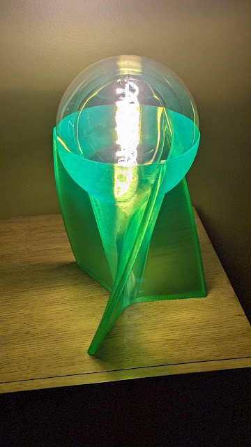
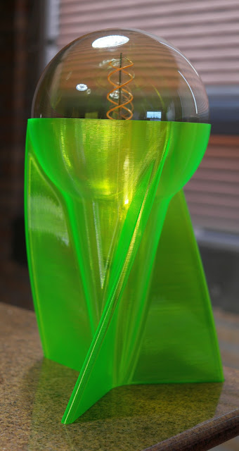
For some reason, I find myself designing and printing a lot of lamps. Here's the latest, designed in Fusion360 to fit a Feit Electric G63 vintage LED filament bulb that is 8" in diameter.
I like combining the antique look of the bulb with a "modern" base- it looks like something out of an old Buck Rogers movie (the movies from the 30s and 40s, not the awful TV series from the 80s).
The lamp base prints in vase mode. I printed it using PETG, a 1 mm nozzle, 1.2 mm line width, 0.5mm layer height, in about 4 hours at 30 mm/sec. Prusa Slicer vase mode has been broken for years and leaves a seam down the side of the print, so I sliced with Cura. No seam at all!
The overall height is 400 mm, the print is 300 mm tall. The bulb barely rises above ambient temperature, even after hours of operation, so there's no danger of melting or softening the PETG print.
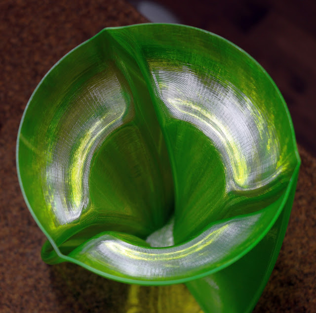
A look down inside the print. You can see the tiny facets that make up the "curved" surface of the print. Maybe I need to export the STL file with even smaller segments.
Power off.
Power on- the bulb socket is quite visible at this angle. View it from a little higher or lower and the socket all but disappears due to the way the print layers scatter light.
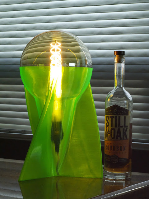
Bottle for scale...
I'll probably print a cone using opaque white filament to cover the socket for this lamp. I'm also going to try printing the whole thing in opaque filament to see what that looks like. I'll post pictures when I do.
The Fusion360 Step file is here. You'll need a 280x280x300 mm (or larger) print capacity machine to print it, and I recommend a 1mm nozzle. You'll find the lamp is saved as a solid object. In the slicer you will use vase mode which will have no infill, a single wall, and no top layers. I printed in PETG, used 3 or 4 bottom layers, and set the line width to 1.2 mm. The resulting print is quite sturdy and very tough. I drilled a hole between the fins near the bottom of the lamp to feed in the line cord because I thought it would look better than running the cord out through a hole in the edge of one of the fins.
When you're wiring things like 3D printers, sand tables, model train layouts, and almost anything else, you often need to use wires to connect things that are separated anywhere from a few cm to a few meters. If you want to do it neatly, you want the wires twisted together, especially if they carry motor or bed heater currents. Twisting wires carrying high currents helps prevent them from inducing currents in adjacent wires.
A few years ago I designed a wire twister and posted it on Youmagine.com. It was a simple, two-part 3D printed tool. The spinning part had screw clamps to hold two wires and a hex shaft to fit in an electric drill/screwdriver. The fixed part was intended to be held in a bench vise. The wire clamps in both parts used screws to hold the wire tightly, so you had to use a screw driver to secure each end of each wire, creating four opportunities to stab yourself with a screwdriver in the process. Operation was simple- just pull the wires tight and pull the trigger on the drill. Bob's yer uncle, instant twisted wire pair!
First generation wire twister. A similar piece held the wires in a bench vise. The screws proved hazardous.
A few days ago, I got an email notice that my old wire twister design was added to someone's collection at Youmagine.com. That same day I had demonstrated Wago lever nuts to my boss who is getting into model train layouts. And then, just like this old commercial...
...something clicked and I realized I could redesign the wire twister to use Wago lever nuts so all you'd have to do is lift the levers, shove the wires into the holes, snap the levers down and spin. No more screwdriver, no more risk of stab wounds! Wagos and 3D printing are the greatest combo since peanut butter and chocolate! The Wago 221-412 lever nuts are good for 24-12 gauge wire, solid or stranded, so they're good for almost any wires you'll ever need to twist.
The New Spinning Clamp Design
I previously designed some printable screw-down mounts for the Wago lever nuts and they worked very well. The lever nuts snap into the mounts so securely you have to use a screw driver to pry them back out. This is the basic unit I started with for the screw-down mounts, and for the new wire twister design:
I grabbed the design for the Wago holder above and reworked it to include a hex shaft to go into a drill:
The model for the Wago lever nut came from partcommunity.com and is supposed to be accessible from inside Fusion360 (Insert>Insert a manufacturer part). It refused my login name/password when I tried to insert the part that way, so I just logged into the site in a web browser, downloaded the .stp file, then "uploaded" it to Fusion360. The model isn't very detailed, and doesn't include the concavity on the sides of the part that allow it to be held in place by the bumps inside my holder design. This is why it is sometimes better to make your own models or at least to measure the parts you want to use in CAD.
The New Fixed Clamp Design
My initial design was for a fixed clamp that you'd use with a C-clamp to hold it on the edge of a table or shelf, or in a bench vise. Then I decided it would be better if the fixed wire clamp actually was a C-clamp so you wouldn't need another tool. Here's what it looks like:
The fixed wire clamp is a clamp! Printed in 3 parts, the thumbwheel, the end cap, and the clamp body.
You can still use a vise to hold the C-clamp, if you prefer, or skip printing the fixed clamp and just hold a Wago in a bench vise.
The hardware consists of a 5/16"-18 bolt, 3-4" long, two nuts, and a washer. Those of you who live in the civilized world (you know, metric) may have to edit/scale the design file a little to use 8mm hardware. Assembly is obvious.
Printing
I used PETG filament for this one because it's pretty tough stuff and can take a lot of abuse. I arranged the parts on the print bed like this:
I have a 1mm nozzle on UMMD and the print came out OK, but I recommend you use a smaller nozzle and print in 0.2 mm layers. The extra cylinder is there to help the hex shaft of the spinning clamp print nicely. You could just print 2 or 3 of the spinning clamps (your friends are going to want one of these tools when they see it) instead.
I printed a bright color so I'd be able to find the thing in the bottom of a bag or toolbox.
The Result
The clamps were printed in 0.2 mm layers. I used contact cement to glue a piece of rubber to the fixed clamp to keep it from slipping when you pull the wires tight. I also used a drop of hot melt glue under each Wago to ensure they'd stay put. Shown here in "storage" mode- a piece of wire will keep the two parts together in your tool box so they don't get lost/separated.
The Wago lever nuts snap into the tool, but dimensions are critical for retention and depend on your printer settings, so you may find that they will pop out of one or both clamps when you twist thick wires. The solution is as easy as a single drop of glue on the bottom of each Wago when you assemble the clamps. If you use ABS to print, superglue will work. You might want to use other glue depending on the plastic you use to print the clamps. Hot melt glue seems to work well on the Wagos.
It's a good idea to glue a little piece of rubber to the fixed clamp so it's less likely to slip when you clamp it to a smooth table top and start pulling on the wires.
In case it isn't obvious from the video above, just cut two wires to equal lengths, strip the ends, and insert them into the Wagos, and snap the levers down. Put the spinning clamp in the chuck of your drill/screwdriver, clamp the fixed clamp to a table or or shelf or put it in a vise, pull the wires tight, and pull the trigger. Keep tension on the wires as they twist, and when you feel you have enough twists in the wires, let go of the trigger. Give the drill a tug to "set" the twist and then release the wires from the Wagos.
Over the last several months, I've been having increasingly frequent problems with my TV streaming. I had a Chromecast with GoogleTV plugged into the TV, and a Bluetooth transmitter that used the aptx low latency codec connected to the TV via optical fiber. I also had some Bluetooth earbuds that used the aptx low latency codec so the audio and video stayed in sync (a problem with my Sony WH-H1000 headphones I got from Costco a few years ago).
The problems I was having with TV streaming were buffering issues with the dreaded spinning circle of dots showing up and interrupting almost everything I tried to watch, whether it was streaming YouTube or Netflix via Wi-Fi, or coming from my Jellyfin server. When I didn't have the circle of dots, I had very low quality video. My Jellyfin server couldn't stay connected and was often unwatchable.
When I was seeing problems, Chromecast always reported excellent signal strength. I'd stream the same video on my computer that is wired directly to the router and there were no issues. So the problem seemed to be the Chromecast dongle. I tried factory reset and it didn't help.
Now I'm wondering if the problems I was having casting video from VLC on my computer to the Chromecast dongle (see the original post, below) were because the Chromecast was starting to crap out.
I did a little research and decided to replace the Chromecast. I ordered an Nvidia Shield TV Pro (NSTP). The NSTP replaced the Chromecast and the Bluetooth transmitter, and even with my Sony Bluetooth headphones that don't have the the low latency codec, audio and video are in perfect sync. Best of all, the video is now perfect, and my Jellyfin server streams perfectly again.
I don't know what happened to the Chromecast- it worked well when I first started using it, but performance degraded to where it was unusable. So, if you're going to run you own server or just stream video to your old TV via Wi-Fi, get the Nvidia Shield TV Pro!
Now back to the original post:
I've been using Plex Media Server to stream video from a computer on my home network to my TV for years. It started out OK, but sometime in the last few years they decided to become a media streaming empire, requiring annual fees and connection to their servers even if I just want to stream stuff from my local HDD. The real kicker is the frequent re logins required. I use TFA with a Yubi key to access my passwords stored in Lastpass. That makes re logging in to Plex a major PITA, especially if I'm sitting in front of the TV with only my phone. To make matters worse, the web address that appears on the TV for logging into Plex doesn't actually work. I don't want any of Plex's streaming services. Why should I have to keep re logging into Plex and paying them an annual fee to access media on a computer on my own network?
I was frustrated, and tried using VLC on my main computer to cast video to the Chromecast With GoogleTV dongle on my TV, but it was very unreliable.
I decided to look for an alternative to Plex and casting via VLC. Searching the term "plex sucks" brings up many hits. It seems I'm not the only one who dislikes Plex. After a bit of digging, I found a pretty good replacement that will stream video from a local HDD to the Roku and Chromecast dongles I have on my TVs. It's called Jellyfin.
With a media server there are a few things to consider:
Can it stream high bit rate video/audio reliably to the targeted receivers? Does the audio (i.e. surround sound) work when streaming video? How do you get media files into the server?
I'll consider each below.
1) Streaming high bit rate video
I did some searching for Jellyfin hardware requirements and couldn't find much specific info, but did find several comments in forums from users who were using relatively low performance computers (even RPi!) to stream 4k video successfully.
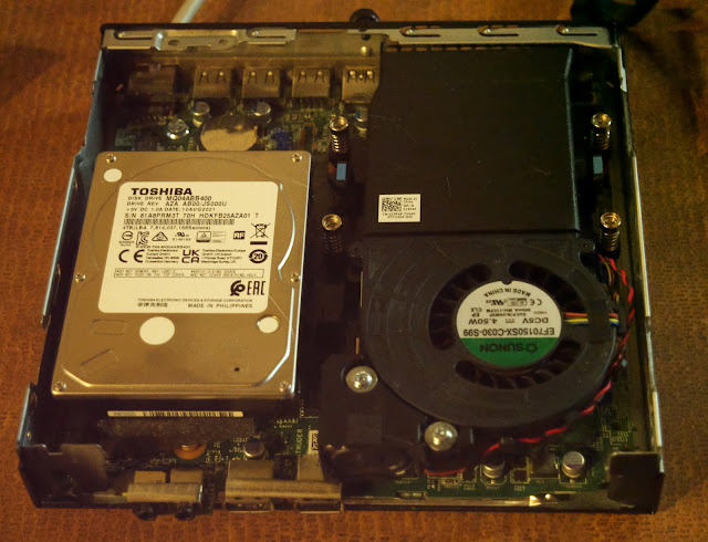
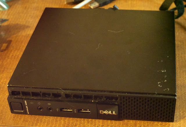
The old Plex server was an ancient desktop PC that used a lot of power, took up a lot of space, and had a bunch of noisy fans. For the new server I decided to try a Dell Optiplex 3020 Micro that I picked up at work when they swapped out all the desktop computers. It has a core i5 processor and 4 GB of RAM.
The server with cover off. The HDD is supposed to fit into a plastic carrier that snaps into place, but this 15mm thick drive won't fit into the carrier.
The server closed up. It's about 7" square and 1.5" high (180x180x38mm)- very small!
Before springing for a big HDD, I wanted to test the whole system to see how hard it would be to set up and if it would reliably stream video to my TV, so I installed an old 250 GB HDD. The Jellyfin web site listed compatible operating systems, and I chose Ubuntu Server 20.04.3 LTS to minimize OS overhead (no GUI, no office apps, etc.).
I downloaded Ubuntu server using a torrent, then made made a bootable USB thumb drive with the disk image using Rufus. I'm not linux master, so I followed instructions for installation on the ubuntu web site, then updated all the OS software, and finally followed step by step instructions at this site to install Jellyfin.
As soon as I got Jellyfin working I put a few media files on the OS HDD and set up the libraries in Jellyfin and tested it. Yes, it worked. In fact, the defaults for everything except audio worked without any messing around. The UI on a web browser and on the TV was great! Jellyfin pulls metadata on the media files from the web and displays everything as well as Plex ever did.
2) Does audio work when streaming video?
I ran into one problem when sending files to a Chromecast dongle on one TV. Chromecast couldn't understand the DTS surround audio streaming from Jellyfin. Chromecast is OK with Dolby Digital (AKA AC3), and Dolby ATMOS. I had to set Jellyfin to mix the DTS surround audio down to stereo for Chromecast to play any sound from files that had DTS audio. Files that used variants of Dolby encoding worked fine as direct stream. It would be nice if there was an option to have Jellyfin do that mix down automatically. The audio mixdown is selected from the Jellyfin home screen settings menu, so it's easily accessed when needed.
3) Getting files to the server
The server is located in the basement at my house and operates headless, so I need to transfer files to it from another computer via the network. The other computer is a Windows machine so I installed filezilla and used sftp to transfer files from my desktop machine to the server. It works perfectly, and very fast.
I use Secure Shell in a web browser to log into the server remotely to do things like update software, etc.
Additional notes:
The Dell computer I chose to use is very nicely made. It's really small, and everything snaps in securely without tools, and there aren't any cables to mess with. Very nice! Except.... the HDD fits into a plastic carrier that snaps into the enclosure. The carrier can only accommodate 2.5" drives up to 9 mm thick, like those used in laptops. The 4TB drive I ordered is 15mm thick. It fit the connector just fine, and didn't prevent the case from closing, but wouldn't fit the bracket, so I cut a piece of foam rubber and put it under the drive to support the free end, then closed the case. I probably wouldn't want to pick up the case and shake it, but short of doing that, the drive isn't going to move.
The computer has a couple USB3 ports, so if I need to go beyond 4TB of storage, I'll add it externally.
I ran into one problem after I installed the 4TB drive and Ubuntu and Jellyfin. When you install Ubuntu server it uses as much HDD space as it needs and leaves the rest of the drive unprovisioned. I discovered this when I tried to transfer a bunch of media files to the drive and transfers kept failing. It was running out of space! Once I realized what was happening, I reinstalled Ubuntu server and this time, when it was provisioning the storage, I made sure to include the empty space on the drive. Yes, I know, there are several ways to do it without reinstalling the OS, but that was easier and faster than trying to figure out how to do it using Grub or other disk manager.
I am sure there are ways to do it, but I did not attempt to set up remote access/streaming from my server across the web.
My TV is mounted on the wall using a corner bracket thing. That means it's not sitting on a piece of furniture on which I could put the sound bar. After about a month of having the sound bar sit on the box it came in, I decided I had to do something better.
The SN11RG sound bar on the finished stand.
Someone at the makerspace was kind enough to leave a box of 1" iron pipe and fittings in the up-for-grabs pile, so I grabbed it, initially thinking I'd use it to make shelf brackets. I considered the possibility of creating a shelf in the corner under the TV, but decided it would be better if the thing was a stand-alone thing that I could move easily in case I decided to move the TV out of the corner.
I measured the sound bar and realized that a piece of 1"x6" wood (actually 3/4" x 5 1/2") would be perfect for it, so I bought a piece of maple at Home Depot, cut it to length (1415 mm), drilled some holes for the flanges, sanded, stained, and finished it. Then I assembled the pipe and fittings and bolted it all together.
1/4-20 flathead screws, washers, and nuts were used to mount the board on the legs.
One of two identical legs, including printed TPU feet to protect the floor.
I decided that it would be a good idea to have some sort of feet to protect the floor, so I designed and printed some using black TPU. I didn't want the feet to be visible, so I made them smaller than the bolt circle of the flanges. They are 2 mm thick, and I added crush ribs to hold them in the pipe.
CAD rendering of one of the feet. The crush ribs have a 28 mm outer diameter to fit into a 1" pipe.
The printed black TPU feet (yes, I know, they aren't perfect, but they're good enough). The crush ribs hold the feet inside the pipe but allow easy removal.
The stand is rock solid so I don't have to worry about Ms. Kitty knocking it over if she jumps up on it.
TSMF had three main problems - it was too big to use at home, a little too noisy, and didn't look like furniture that would be acceptable in my living room. I decided to build a new, smaller table, with a more presentable finish, that I could use as a coffee table. It would have to be the right size, the right height, and as quiet as a mouse. I think I succeeded, though you may not care too much for the finish...
The result is "Arrakis", named for the sand covered planet in the Dune novels by Frank Herbert.
Arrakis, in all her glory! I gave her a haircut after this photo was taken, trimming off the fur peeking out from under the glass top inside the box.
Here's what I did that is different from TSMF.
The Mechanism
The Arrakis mechanism is smaller, and closer to the floor to make it more usable as a coffee table.
TSMF's mechanism had a couple problems. The 45 mm square t-slot frame was a little flexible. I found that the belt tension was sufficient to cause the Y axis frame rails to bow outward. When X direction motion reversed, especially near the center of the table, the entire X axis would shift in the Y rails and make a clunking noise. I made a partial fix by bracing the frame with crossbar made of wood that helped prevent the rails from bowing, but it was still a problem.
I wanted a definitive fix for that problem in Arrakis so I spring loaded one of the Y axis bearings so that the X axis couldn't move back and forth between the Y axis rails, even if they bowed outward. I had also had a failure of one of the Y axis blocks due to poor design (the X axis tube was tight fit to the blocks and tended to split the printed layers apart). The new block design was made in two pieces, with screws that clamped it together over the X axis guide tube.
Here's the bearing/pulley block that has the sprung bearing. The light orange part is a PTFE bearing that fits in the t-slot of the XY mechanism's frame. The block at the other end of the X axis is identical, except the PTFE bearing is screwed to the block instead of sliding on pins.
The right side Y axis bearing/pulley block that has the sprung bearing as seen in the video, above. The three screws hold the two printed pieces together, clamping the X axis guide tube (black). One screw passes through holes drilled in the X axis guide tube. The pulleys are made from stacked F625 bearings and held in place with 5mm steel pins (you can see one pin sticking up a bit at the top).
This is the left side Y axis pulley/bearing block. In this one, the PTFE bearing that fits into the t-slot is screwed to the block. There's a flag for the Y axis opto endstop glued to the top of the block.
Another view of the right side Y axis bearing/pulley block.
TSMF's magnet carriage was also a problem. The magnet fit into a square hole with a light spring that kept the magnet pressed against the bottom of the sandbox. Dragging the magnet against the wood was noisy (and created dust under the table). It got even noisier when the motion changed direction. The magnet would rattle in its hole in the carriage and against the bottom surface of the sandbox.
In Arrakis, I wanted the quietest possible operation, so I redesigned the magnet carriage. Now the magnet is glued to the carriage so it can't rattle, and it is separated from the bottom of the sandbox by an air gap.
The magnet carriage. The screws that hold it together also help anchor the belts. The belts are folded over the screws and clamped against themselves with teeth interlocked in narrow slots. You can just see the PTFE bearings contacting the X axis guide tube. There are four such bearings and their contact pressure on the guide tube is adjusted using shims made from soda cans.
The magnet is glued to the top of the carriage using silicone glue. The "blade" is the flag for the X axis optical endstop. In order to home the X axis, the Y axis must be homed first.
This video shows how the pieces of the magnet carriage go together. There are four screws that hold the printed pieces together at the corners and serve as part of the belt clamping system. The blue parts are PTFE blocks that act as bearings to allow the part to slide on the X axis guide tube. I used shims made from soda cans to adjust the pressure that the bearings apply to the X axis guide tube.
Here is a video of the mechanism running at 200 mm/sec with plenty of close-ups of all the parts:
The Electronics
When I switched from steppers to servomotors in TSMF, I used two power supplies- one 150W supply powered one motor and a 200W supply powered the other motor, the controller board, and the LEDs (the LEDs had two buck converters to step the 24V down to 12V).
The schematic is the same as TSMF, except that I added a separate power supply (not shown) for the Duet controller board:
As I was working on the Arrakis mechanism I learned something about servomotors the hard way. I had finished putting the mechanism together and wanted to test the motion so I loaded a TSMF pattern file and started it up. I didn't consider what might happen running a large pattern on a smaller table. The magnet took off and quickly slammed into the end of one of the axes, coming to a loud and abrupt halt. The machine stopped dead and wouldn't respond to commands.
I did some research and found that that is a well known/understood problem among people who use servomotors. The problem is the kinetic energy of the system gets turned into electrical energy when the mechanism is blocked. That causes a voltage spike on the power supply line which, in this case, killed a power supply and the Duet WiFi controller board. Shortly after this, the small buck converters that were powering the LEDs from the same power supply also failed. I was lucky that the voltage spike didn't also kill the integrated driver in the motor.
I replaced the power supply, Duet WiFi board, and the buck converters (this time using higher power units), and added a separate power supply for the Duet board.
I found a protection circuit that will prevent power line spikes coming from the motor from doing that sort of damage, and have all the parts in hand, but need to come up with a circuit board for it. Watch for a blog post on the circuit board. In the meantime, I have provided the controller board with its own power supply to keep it separate from the motor.
Protective circuit for servomotors. If the voltage at the motor gets higher than the voltage from the power supply, the transistor turns on and shunts the voltage to the 33 Ohm resistor. When the motor voltage drops back to the supply voltage the transistor shuts off and everything operates normally.
In TSMF the electronics were mounted in a box that was attached to one of the table's legs. In Arrakis I mounted all the electronics on an aluminum plate screwed to the mechanism's frame. I used a Duet WiFi controller board so I wouldn't have to have a control panel on the table. Power on/off is controlled with a foot switch on the line cord. I used a white line cord because the table is best viewed in the dark and I didn't want to be tripping on the cord in a dimly lit room.
Electronics mounted on aluminum panel that's bolted to the t-slot frame. Left to right, 150W 24V power supply, Duet expansion board, Duet WiFi controller board, 200W 24V power supply. The other side of the plate has a small 24V supply for the controller board and two buck converters to power the LED strips in the sand box.
CAD rendering for positioning electronics.
Expansion board (left) that provides step/dir/enable to servomotors, Duet WiFi controller board, and 200W 24V power supply.
The Sandbox
TSMF's sand box was made with 1 x 8" pine sides and a 1/2" plywood bottom. Pine isn't very good for much besides coffins, and is too soft- it will show every little bump. I wanted a different look for Arrakis so I ordered some red and blue fur that matches the LED lighting inside the table. I also wanted to use a thinner bottom panel so I could put an air gap between the magnet and the box to reduce noise.
I found that running TSMF at high speed would throw the sand with some of it sticking to the cover because the cover was too close to the sand. I had to open it up to clean the cover frequently. I designed Arrakis with the mechanism close to the floor and the glass cover about 230 mm above it, at coffee table height, to minimize cover cleaning.
As you may have seen in some of my photos and videos, I have a cat. She has one bad habit- she likes to chew on wires. I designed Arrakis so the sandbox would come down very close to the floor to keep Ms. Kitty away from wires and belts. If you build something like this you might also want to design it to keep pets or little kids away from wires, belts, pulleys, and motors.
The sides of the sandbox are made of 1/2" Baltic birch plywood. The corners are held together using aluminum corners of the type used to make musical instrument cases, and rivets. That's one decision I regret for reasons I'll explain below.
The bottom of the box is made of 1/4" Baltic birch plywood. That allowed me to put the air gap between the magnet and the bottom of the box which reduced noise. During construction and testing the mechanism with the unfinished sandbox in place I noticed that the steel ball rolling on the plywood bottom of the sandbox made quite a bit of noise. I wanted to try to reduce ALL noise, so I did some experiments and found that a rubber coated steel mouse ball was very quiet (unfortunately, large diameter). Then I tried a steel ball rolling on a rubber sheet- also very quiet.
I ended up gluing a sheet of black EPDM rubber roofing membrane to the bottom of the sandbox. That created another problem- it caused the plywood to warp. Eventually I got that under control and it went into the sandbox without any problems. The corners of the sandbox and the bottom edges are sealed with black silicone and the inside of the box is painted with matte black paint.
Gluing the rubber sheet to the plywood caused the wood to warp! The PVC pipe was used to roll out bubbles trapped under the rubber. I later added staples to the edges of the rubber sheet, in case the glue ever lets go. I was able to get the warp out by putting a couple pieces of wood under the ends of the board and standing on it a few times. It also seems to have settled a bit with time.
The outside of the sandbox was finished by gluing on pieces of high density 1/2" upholstery foam covered with blue and red striped fur cloth to match the LEDs that light up the table. The cloth was folded over/under the side walls and stapled to the plywood. The seams were hidden by cutting the cloth on the red/blue lines and carefully matching them up before stapling. As each piece was mounted, I glued the edges of the cloth to the foam, then carefully matched up the red-blue lines on the cloth so there would be no break in the pattern all the way around the table.
One corner of the sandbox showing the aluminum extrusion, rivets, printed spacers.
The sandbox was assembled on the granite counter top so the edges would all be in the same plane. The narrow strips are the supports for the plywood bottom of the box.
Installing the fur cloth. I painted the inside of the box black (well, more like charcoal grey), then cemented high density upholstery foam on the sides using a spray foam adhesive, then cut four pieces of the fur cloth (note the fuzz on the floor and in the sandbox), then stapled the cloth to the wood. You can see some printed neoprene spacers (red) that lift the box just enough to create the air gap between the magnet and the bottom of the box. The neoprene spacers were later replaced with printed TPU parts.
The box with the bottom in place and the cloth stapled down. LED strips are not yet mounted. I cut each piece of cloth along the red/blue lines and glued the edges to the foam so that there would be no visible seams where the different pieces of cloth meet. The fur hides the seams perfectly and I have a difficult time finding them even though I know they are there.
The top of the table is a piece of tempered glass that I bought for $6 via Craigslist. I made a frame for it out of oak by cutting the boards to length, milling in 1/2 lap joints at the corners, gluing them together, rounding the corners, sanding, staining, and finally finishing with oil based polyurethane. There is a black painted pine subframe that supports the glass. Eventually, I'll seal the glass to the top with silicone so that if some dope (probably me) spills a drink on the table it won't end up in the sandbox.
Staining the frame. The wood is 1"x4" oak cut to length and sanded smooth, with half-lap joints at the corners. The corners were rounded with a couple cuts with a pull saw and then sanded. After staining, I applied a few coats of oil based polyurethane, then added a sub frame to support the glass top.
The LEDs are the same strips used in TSMF, cut shorter. The printed plastic clips to hold the LED strips in contact with the aluminum L channel heatsink did not inspire confidence, so I drilled a bunch of holes at every third LED and used zip ties to hold the LED strips down. They are covered with some black painted polystyrene trim boards that hide the aluminum heatsinks and prevent direct view of the LEDs.
I discovered that the black paint didn't stick to the aluminum corners of the box very well and quickly chipped the paint when installing the LED strips. I touched up the paint afterward, but I expect it will probably start peeling soon. I may need to put some sort of primer on aluminum when it's time to fix the paint again.
cutting fur cloth with scissors- next time (?) cut from the back with a razor knife instead, and keep the vacuum cleaner close by.
aluminum corners for the sandbox, and the rivets used to hold them- paint doesn't stick well and the rivets take a lot of space. I think it would have been better to use 2x2 wood pieces and screws.
black EPDM rubber on the bottom of the sandbox- should have used white, and maybe faux leather instead of EPDM. Contact cement would have probably been better and caused less warping of the 1/4" plywood, too.
LED wiring- I need to put more effort into creating contacts on the sandbox and frame mechanism to connect LED strips just by dropping the sandbox into position on the frame. Maybe adapt some battery contacts...
At the Makerfaire in Milwaukee a few weeks ago I spotted a tool I had never seen before sitting on a table. I picked it up and played with it for a minute and was hooked. It belonged to Markus, one of the Makerspace members who happens to be German, and has a great collection of super high quality European hand tools. Thanks Markus for showing me yet another great tool!
The particular tool I am referring to is a Knipex Pliers-Wrench. It is essentially an adjustable wrench, but unlike the type with the little worm gear to set the jaw spacing (which always slips and requires readjustment multiple times almost every time you use it), it operates like a pair of pliers. What makes it a wrench? Unlike normal pliers, the jaws are smooth and remain parallel at all times. The tool is intended for gripping the flats on nuts and bolts, not for grabbing pipe. You can still use it to crush and bend things like pliers, but you're not going to hold or turn pipes with it (Knipex makes other great tools for that).
This is the exact tool I bought. $48 via amazon.com Nope, not cheap, but in a world where Apple sells $19 microfiber cloths for cleaning ipads, a relative bargain.
The Pliers-Wrench comes in many sizes, but the two most useful for everyday stuff are probably the 125mm and 180 mm models. The 125 mm version has very narrow jaws that can grip thin nuts like the jam nuts used to hold bearing cones in bicycle wheels (for bikes without sealed cartridge bearings). The 180 mm version that I bought is a bit longer (more leverage) and has wider jaws and can be used on nuts/bolts up to 40 mm (1 1/2")! That makes it a great tool to carry on a bike or in your car, truck, boat, or RV, because it can grip any size nut or bolt, metric or imperial.
You adjust it to the size of nut you're trying to hold by pushing down on the spring loaded pivot and sliding the jaws to the needed size. Opening and closing the handle through their full range gives about 6 mm (1/4") of adjustment range at each of the pivot settings. That also means it will work similar to a ratchet wrench if you loosen your grip on the handles as you rotate the wrench on the nut. The grip strength is very high and I was able to crush the edge of a penny with it.
There are many reviews of the Knipex Pliers-Wrench on youtube. Here's one of them:
Highly recommended (and no I didn't receive any compensation for saying so).
I recently added an LG SN11RG sound bar to my TV (got it on sale for about 1/2 price!). It's pretty deluxe, and connects wirelessly to the woofer and two rear surround speakers. My setup is a little less than ideal, but I'm kind of forced to position things the way they are due to the many windows in my living room. By less than ideal, I mean the TV is in one corner of the room with the sound bar, and the surround speakers are on end tables on either end of my couch.
The end tables are not matched and one is 30 mm higher than the other. I wanted to put the speakers at equal height, so I designed two stands, one 200mm tall and the other 230 mm tall to make up for the difference in end table heights.
It took two attempts, but I matched the bottom of the speakers perfectly and have the rubber feet sitting in little concavities in the tops of the stands. A single M4 screw attaches each stand to its speaker. The first design had three feet to sit on the tables, but I felt like it wasn't going to be stable enough so I redesigned them to have 180 mm diameter round bases.
The stands are printed using PETG with a 1mm nozzle with 1.2 mm line width, two perimeters, and zero infill. There's a cone in the center of each stand that allows me to get a long 3mm hex screwdriver in to tighten the M4 screw that holds the stand to the speaker. I added some modifiers with 90% infill at the top of the stands to allow clean printing of the concavities for the speaker's feet.
This is one of the stands highlighting the cone that runs through the center of the stand to allow tool access for installing an M4 screw.