Saturday, May 13, 2023

A Music Jukebox with 4k Visualization


Update 9/23/24

I have set up a proper stereo system in my living room that sounds much better than the sound bar, so naturally I wanted to connect the jukebox PC (runs windows 10) to the stereo system. I tried the analog audio out from the PC but the sound quality wasn't great. I decided to try adding a USB DAC to the system, and did some online research and found a lot of people seemed to like the SMSL SU-1 DAC that sells for $80 on amazon.com. I ordered one and tried it out. It just plugs into the PC with a USB C cable (that also powers the DAC). It was immediately recognized as a "USB headphone" and audio switched from the sound bar to the DAC. 

I buy a moderate amount of stuff from China and my experience is that it almost never meets advertised specs, and drawings on web sites are almost always different from the parts you receive. I found a technical review of the SU-1 DAC at audiosciencereview.com that includes measurements of the DAC's performance. In this case the measured performance matches the promised performance on the SMSL web site. It's a VERY good DAC, especially considering the low price.

Audiosciencereview.com also just did a tech review of the VRDS-20 CD player which I happen to own and is connected to the living room stereo system. Their tests show that the SU-1 DAC is much better than the one built into the CD player. I tried comparing the two and found the measured differences are inaudible to me when the CD player is playing music.


Update 7/7/23

I have a server PC that runs Jellyfin to send video to the Nvidia Shield TV Pro connected to my TV and runs the Logitech Media Server to send music to my Squeezeboxes and to the sound bar connected to the TV. I recently realized I could just run Squeezeplay, a software player that plays music streamed from the Squeezebox server, on the Jukebox PC directly, so I don't really need another music player on the Jukebox PC running MilkDrop 3, and I don't need to store any music files on that PC. Control is still a little wonky- I can select music and playlists using my phone or any computer on my network, but I still have to manually start Squeezeplay and MilkDrop with a keyboard/touchpad connected to the Jukebox PC.


Now back to the original post:

I recently got a wonderful LG C2 77" 4k OLED TV to replace my 15 year old, 52" Sony TV, and it got me thinking about a project that I've had in mind for a few years. I've always liked music visualizers that generate trippy graphics in sync with music, such as the MilkDrop visualizer in WinAmp (remember WinAmp?). There are other visualizers, but none that I have seen (and I think I've seen them all!) that compare to MilkDrop. Someone has updated both WinAmp and the MilkDrop visualizer packaged with it in a program called Wacup that you can DL here

I decided to try out Wacup on my 9 year old ThinkPad W530 laptop that I use as a desktop machine for CAD, etc. That computer has an Nvidia Quadro K1000M graphics card with 2 GB of dedicated RAM. First I tested it on the QHD (2k) display on my desk and results were pretty good. It was able to drive the monitor full screen at 2k resolution and 60 fps for many presets, though some bogged down or failed outright. Next I tested it on the TV at 4k resolution. I bought a mini DVI to HDMI cable via amazon.com and hooked it up. The result was pretty good, but many of the presets slowed down or failed and the screen went blank, something I attributed to the relatively low power of the graphics board in the laptop.

A little later I found that someone had rewritten MilkDrop as a stand alone program (MilkDrop 3) that will sync trippy visuals to any audio in the computer, and added a lot of new capability to it in the process. I'm not a huge fan of the WinAmp UI, and wanted to try the added features in MilkDrop 3 so I installed it and used VLC for further tests.

When MilkDrop 3 ran on my ThinkPad, the Windows task manager showed that only one processor of the i7 CPU in the laptop was operating at 20% while the GPU was getting slammed (>80%) by many of the presets. So I knew that I needed to focus on the GPU and started a survey of low cost graphics cards to see what kind of PC I could build for as low cost as possible to get 4k at 60 fps.

This posed a problem. How do you know what sort of graphic card specs you need to display the visualizations at 4k and 60 fps? I was posting questions about graphics card capabilities in an online forum and someone suggested that running MilkDrop at 4k resolution was pointless because nothing stays on the screen long enough to see that level of detail. Spoiler alert: now that it is working, I'd say that was wrong. There is a lot of very fine detail in many of the presets that looks great either close to the screen or from far away. I guessed that a card with maybe 10x the performance of the Quadro should do the job, so I started looking for card model numbers that would do that in order to get some idea of what a card would cost.

Along the way I found some interesting videos on youtube showing how to connect a gaming type graphics card to a small form factor PC, like this one: 


The GTX 1650 card in the video was about $180 new, and its performance seems to be 10-12x that of the Quadro, so I thought it might be a good one to try. I started pricing everything out and quickly came up to about $450-500 to build a PC to do the job, but thought it would look pretty bad when it was done (like the one in the video above, though it will probably be hiding inside a cabinet under the TV). That seemed like a little too much to spend to end up with an unsightly mess.

I was about to shelve the idea and wait for technology to catch up (i.e. get cheaper) when I saw a deal on a refurb HP desktop PC from woot! that had an i7 6700 CPU, 16 GB of RAM, and most importantly, came with an Nvidia GTX1660 Super graphics card (6GB of DDR6 RAM) for $439.

The GTX1660 S card has about 20x the processing power of the Quadro K1000M, and 6GB (3x the Quadro) of much faster DDR6 RAM, so I assumed plenty of juice to run MilkDrop visualizations at 4k 60 fps without too many problems. I suspect the cheaper GTX1650 has sufficient horsepower to do the job, but didn't get a chance to test it. If anyone has any lower end graphics cards to share I'll be happy to test them and report the results.


Initial Tests

After setting up Windows 10 Pro (already installed on the computer), installing MilkDrop 3, copying some music files to the HDD, and installing the latest gaming driver for the graphics card, I connected it to the TV and tested it with VLC playing the music.

I am happy to report it works very well! Visuals are detailed, super smooth at 4k resolution and 60 fps, and respond well to the beat of the music with hundreds of presets tested. There are no slow downs or blackouts, and of course, everything looks great on the big OLED display. Audio gets sent to the TV via HDMI from the computer, and from the TV to the sound bar via the eARC HDMI connection. The visuals sync with the music very well in this arrangement.


Running full screen at 4k resolution and 60 fps, CPU use is minimum- I've seen it go as high as 15%, so you might be able to use a much lower spec CPU, and the GPU rarely gets above 40% utilization. This report is generated by GeForce Experience, installed along with the gaming driver for the graphics card.


MilkDrop reports the name of the preset and frame rate when you hit the F3 and F4 keys. At 4k full screen I've never seen the frame rate drop below 58 fps on any preset.


One thing that concerned me about the GTX1660 S graphics card was the big fan on the GPU heatsink. I was afraid it might be pretty noisy. So far, it has been super quiet, even after hours of continuous operation.

During initial tests I ran into a few problems- every few minutes, for no apparent reason, the audio would drop out for a fraction of a second, and after about 10 minutes or so the TV would go black and the audio would switch to the computer's internal speaker. 

Win 10 defaults to turning off the display after 10 minutes without mouse or keyboard input. That's an easy fix- go to settings>power and battery>display and set the screen to blank "never". That fixed the black screen and audio switching to the PC's internal speaker.

I switched to the Groove Music program that comes with Win 10, and found it worked without dropouts. There's probably some setting in VLC that can fix the dropout problem. I will probably try out a few other music players to find the one that has a UI that I like, and performs well without dropouts.

I shut off all the audible notifications in windows so none of those noises happen while I'm listening to music. I also bumped up the size of the text and mouse cursor on the screen so I could operate the computer from the couch.


Controlling it

I needed a convenient way to select music to play, construct playlists, and start and stop them from my couch without having to have a keyboard and mouse plugged into the computer. For now I'm using Groove Music player to play the music stored on and selected from a local HDD in the computer (it came with a 3TB drive), and using a miniature Bluetooth keyboard/trackpad that doesn't seem to work very reliably, so I'm going to look for something else to use.


Mini Bluetooth keyboard/trackpad that sort of works, but not very reliably.


I use a Logitech MX Keys Mini Bluetooth keyboard at my desk computer that is just about 100% reliable. I'll may just add a Bluetooth mouse and take it to the couch when I'm setting up the music and visuals, or since I need my laptop to control Arrakis, maybe I'll set up remote desktop with the music/visuals computer and use that for the ultimate remote control.


More Presets

MilkDrop 3 comes with 500 presets when you download it. 

500 not enough? You can download 9,795 more presets here.

10,295 not enough? You can download 48,000 presets here (includes the 9,795 above).

You can find instructions for creating your own presets here. At first look it doesn't seem easy- it may take some study and experimentation.

One thing I found is that a lot of the presets include some very bright, flashing lights and colors that can be a strain to look at for even a few seconds (and possibly cause epileptic seizures in susceptible people). I am going to start going through the thousands of presets and see if I can create a bundle of them that do not flash that way. Watch this post for a link to them as I get going on it.

I have also noticed that some of the presets don't seem to have any beat detection at all and just do their own thing. I'll try to separate those from all the others. MilkDrop will run without any audio input and still make some very nice patterns to watch.

Here's what some of the double-presets look like in MilkDrop 3:


Friday, May 12, 2023

Bicycle Disc Brake Pad Sanding Tool


Those of you with bikes that have disc brakes know that sooner or later, they are going to start squealing. In my experience, besides being annoying as hell, when they are squealing, they aren't stopping the bike very well, so you really need to stop them from squealing. 

One common maintenance step to relieve squealing is to sand the pads. This can be tricky to do without sanding the skin off your finger tips because the pads are small and thin. I decided to make a tool that would make it easier to sand the pads without hurting my fingers.

The tool is 3D printed, of course, and holds two pads for easy sanding without injury. I designed it to fit the Shimano type pads that fit my bike's brakes, but a similar design should work for any type pad. Just set a sheet of sandpaper on a smooth, flat surface, set the pads on the sand paper, position the tool over them, and have at it. The pads fit into 2.5 mm deep recesses and are held captive in the tool as long as you are applying downward pressure on the tool.

It was about a 10 minute design in Fusion360. First I modeled one of the pads, measuring everything to within 0.1 mm using a caliper. Then I created the tool:


The tool, printed in PETG, 1 mm line width, 0.5 mm layers, 25% triangular infill. It took about an hour to print at 30mm/sec.

The tool with a couple used, squealy brake pads ready to sand.

The tool and pads after sanding (and a rinse in 91% IPA), ready to go back on the bike and provide a couple more weeks (!) of squeal-free braking.

The CAD file (STEP) is here.


Saturday, April 8, 2023

Aperiodic Monotile

 What?

Some folks recently came up with a single shape tile (a monotile, or einstein tile) that can tile a surface without the possibility of generating a repeating pattern. There's a simple explanation here:


I first saw mention of it on Hack-a-day (I think, but I can't seem to find it there now), followed the included links and immediately drew a copy in Fusion360 so I could print a bunch of the tiles and play with.  A couple days later the NY Times ran an article about it and then Stephen Colbert was joking about it on the Late Show (another one I can't find a link for - don't get old!).

The basic shape, called a "hat" (I think it looks more like a V-neck tee shirt) by the inventor is derived from 3 hexagons, which is how I created the shape in Fusion360.

Here's one of the images that I used to create the Fusion360 model:


Notice that the dark blue tile is a mirror image of the other, lighter tiles that are all the same shape.

I drew a single tile in Fusion360, used one of the diagrams to lay out a bunch of the tiles, then pulled back the perimeter by 0.3 mm. Since each tile was a copy of the original, modifying the original pulled back all the perimeters by 0.3 mm. Then I printed them.

The dark blue tiles in the image above are mirror image of the other tiles that are all the same shape, so I printed a set of those by using the mirror function in Prusa Slicer.

The tile layout I used in Prusa Slicer- these are the mirror image tiles (dark blue ones from the drawing).

I printed the tiles on UMMD in red, white, and blue (mirror) PETG so I could play with them a little. UMMD has a 1 mm nozzle and printed in 0.5 mm layers. The base of each tile is just 1 mm thick and the walls are 1 mm thick, so it takes very little filament to print. They print quickly, so you can produce hundreds of them in a couple hours.

A single tile- the walls are 1 mm thick and 5 mm tall, the base is 1 mm thick (2 print layers). These print fast and use little filament- about 1.3 g per tile.


Here are some of the tiles laid out on Arrakis. Note the hexagonal holes in the pattern- that's because I did not use any mirror image tiles in the layout. If you don't use any mirror image tiles, I think you'll always have holes of some sort in the tiling. Using the mirror image tiles allows patterns that have no holes or gaps.

The paper that describes these tiles and the mathematical proof of aperiodicity is here.

My Fusion360 file is here in STEP format and here in f3d format

Update: 4/23/23

I made a storage box for the tiles, shaped like... what else?


The box is an oversized tile with a 15 degree twist, with a matching lid.


Have fun!


Monday, December 5, 2022

Some minor updates to UMMD

Several months ago I noticed that the white overhead lights in UMMD were flickering. It wasn't a high priority so I let it go for a while. I recently got the urge to fix it, hopefully permanently, so I ordered some 12V LED bars to replace the old 24V LED strips that were in there.

The old LED strips, looking up at the "ceiling" in the printer; some dead LEDs, and some flickering. The front of the printer is at the bottom. The aluminum bracket with green clips is the top-down UV lighting.


I found some 12V, 6000K LED bars at amazon and ordered them, pulled the old white LED strips off the ceiling, and installed the new LED bars. I used some Wago lever nuts to connect the bars together and to 12V.

The new 12V LED bars came with mounting hardware. They are good for about 3W each.


The new LED bars installed in the printer. 

One thing I didn't like too much about the printer was the way I had to cut notches in the upper front cover to accommodate the XY stage belts because the motors are mounted outside the printer enclosure. I always thought it looked sort of ugly. I thought about it a little and realized I could just print some pieces to fit on the frame, then cut nice square notches in the front cover and it would probably look nicer, and might even seal a little better to keep the heat inside the enclosure.

Here's the B motor with notches cut in the front cover for the belt and the bolts that hold the XY stage together.

I got to work in Fusion360 and came up with two parts to print that look a little neater. I thought about printing a single piece to fit across the width of the front panel, but realized that unless I printed it vertically, the bed wasn't big enough to make it as a single piece. So I split it into two pieces.

The new print (yellow) at the A motor. There's a rectangular hole through the print for the belt, and a 5mm deep groove on the top and side to accommodate the front cover. There are also holes in the print to cover the two bolts that stick up. The front cover now has clean, rectangular cutouts on the two sides. The printed parts are held in place by tangs that fit into the t-slot on the left and right side and t-nuts and screws on the bottom.


That's it. No big deal.


Wednesday, November 30, 2022

Ikea Frakta (Blue) Bag Handle

 I live about a 100m walk from the garage where my car is parked to my door. I don't like to shop frequently, so I tend to load up, and that means getting multiple bags of groceries from my car to my condo. Someday I'll get some sort of collapsible cart to roll the stuff to my door. Until then I use a different means to schlep the groceries from the car to my door.

I keep two, blue, Ikea Frakta shopping bags ($1 at any Ikea store) in my car to carry multiple bags of groceries, or a bunch stuff to take to and from the makerspace, all at once. The only problem is that if the load is heavy, the bag's sewn-on cloth handle crushes my hand. Ouch!

I could have simply cut a slot in a piece of PVC pipe to make a handle, but PVC is hard and slippery, so it might be uncomfortable with a heavy load in the bag. To a hammer, everything looks like a nail, and to a man with a 3D printer, everything looks like a 3D printing project. I immediately thought to use TPU filament so it would feel softer in the hand than PVC pipe, and the ridges from the printing process would make it easy to grip. 

It took about 10 minutes to design the handle and prep it for printing- it looks like a piece of pipe with a slot cut in it! I used generic TPU, a 1 mm nozzle, printing in 0.5 mm layers with 1.2 mm line width at 30 mm/sec with 15% triangular infill, 2 perimeters, and 2 mm top and bottom thickness. It takes about an hour to print and uses 66g of filament.


CAD rendering of the handle. Pretty simple- draw the C shape, extrude, fillet the vertical edges, chamfer the top and bottom perimeters.


This is the handle printed in red TPU. It's rigid, but has just enough give to keep it comfortable. It's 120 mm long and 35 mm in diameter, which might be a little big if you have very small hands.


The handle in place on the bag. It takes a little effort to attach it to the cloth handles, and a little effort to detach it, too, which is good. 


An alternative location to store the handle- use it to hold the bag so it doesn't unfold when you don't want it to.

This handle should work with any other bag with a cloth handle and even dog leashes.

You can download the STEP file here.


Sunday, November 13, 2022

Arrakis 2.0

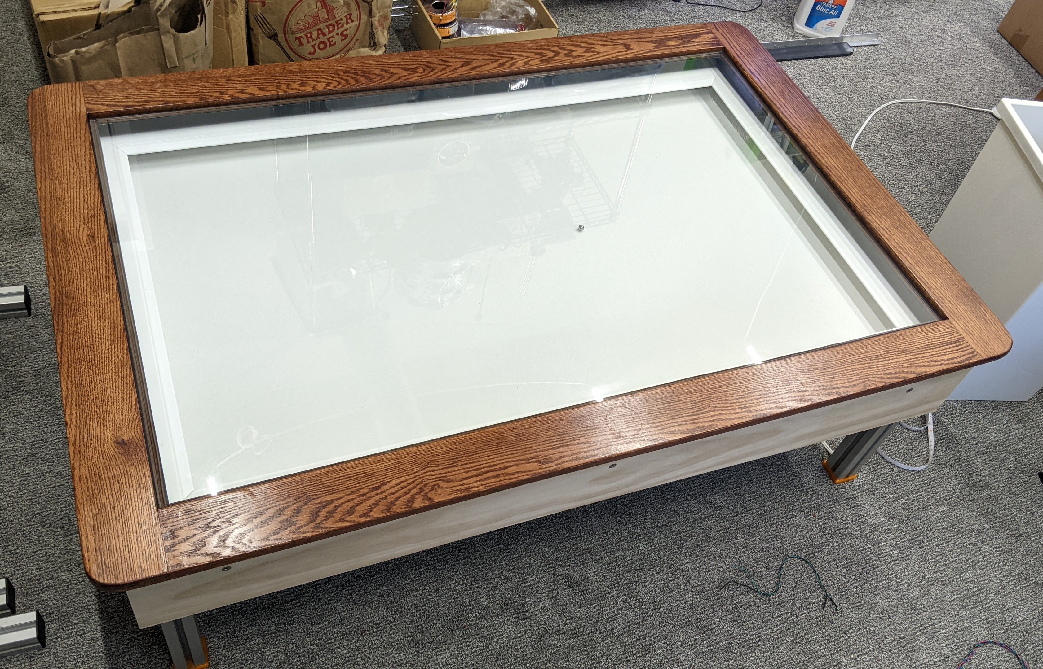
Arrakis 2.0 made it's public debut at the Maker Faire Milwaukee on October 22, 2022, and got a nice write-up in Make magazine.


I liked Arrakis, but found some problems after living with it for a while. 

  1. The bottom of the sandbox was made of 1/4" Baltic birch plywood covered with a sheet of black EPDM rubber to keep the ball-rolling noise down. Most of the time it was fine, but with some patterns where the ball passes over the same area repeatedly, the sand would be pushed away revealing the black rubber. I didn't like that so much.
  2. An even bigger problem was that the plywood warped depending on the weather, enough to close the air gap and the magnet would drag on the underside of the sandbox, making noise and producing wood dust. I put a lot of effort into making it run quietly, so this really bugged me.
  3. Running the table at high speed causes the ball to throw the sand, so in the original design I separated the top and bottom as much as possible so I wouldn't have to keep cleaning sand off the underside of the glass top cover. It worked, but I decided that the bottom of the sandbox, where the drawings appear, was just too far below the top cover, requiring uncomfortable seating to view the drawings. 
  4. In packing up for the Maker Faire I found lots of PTFE dust in the mechanism- PTFE isn't ideal for sliding bearings for this reason.

In the interest of keeping this post relatively short, I won't go into too much detail, but will use lots of photos to show what changed.


Arrakis 2.0
Iced latte! See! I really use it as a coffee table.


Sandbox redesign and build

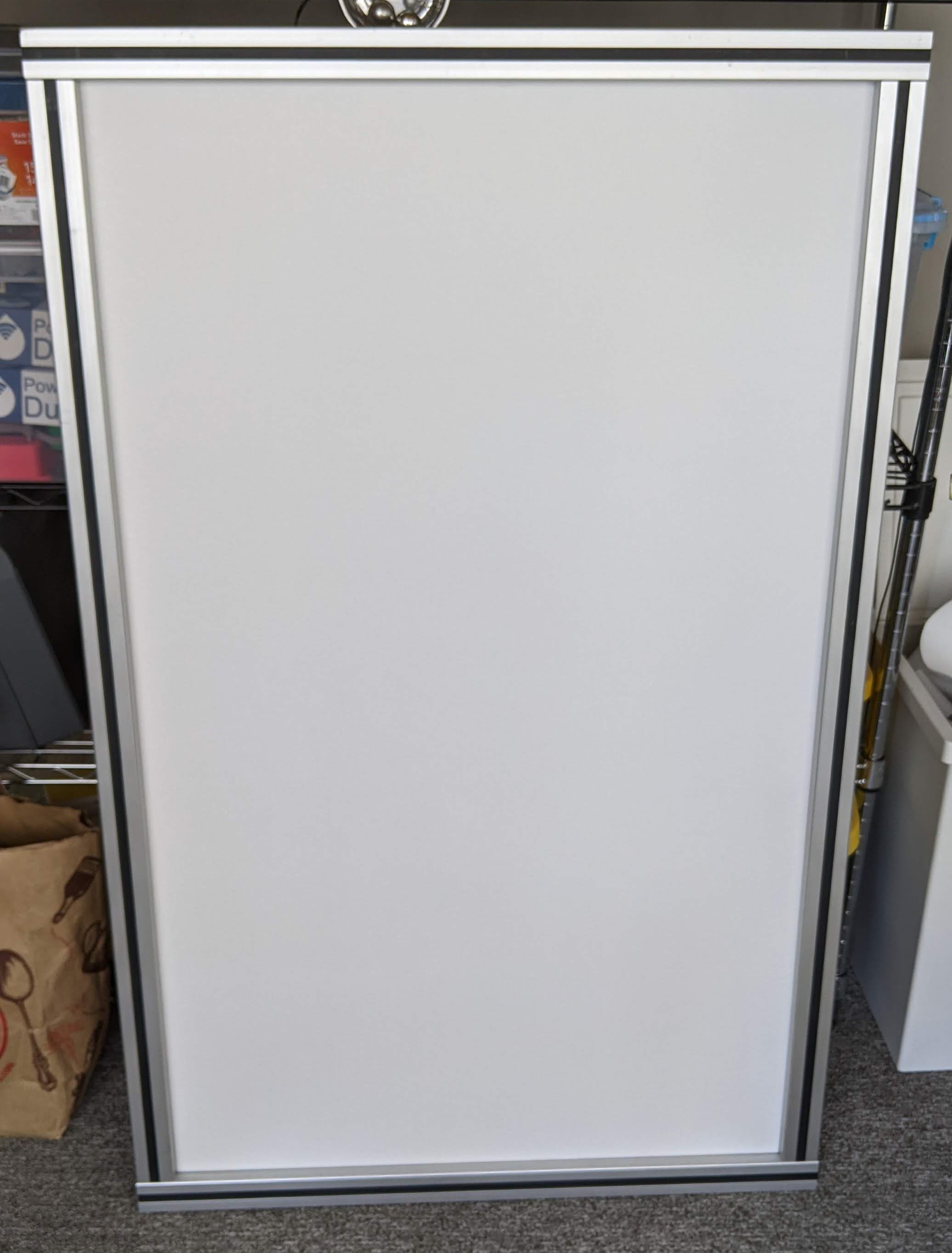
First, the legs were lengthened to raise the XY mechanism higher. Then I built a 45 mm t-slot frame to hold a sheet of 4.7 mm thick tempered glass (same size as the top cover!) and covered the glass with cloth-backed white vinyl. LED strips were mounted in aluminum C channel stock that was screwed to plastic strips that fit into the t-slots in the sandbox bottom frame. A decorative frame, made from prefinished white polystyrene molding, drops into the sandbox on top of the LED C channels. Side panels are made from 1x8" wood and simply bolted to the t-slot frame using t-nuts and countersunk M6 flat head screws.


Sandbox glass bottom sprayed with glue. The glass is the same size as the top cover and is 4.7 mm thick.


Cloth backed white vinyl glued to the sandbox bottom glass. The excess material was trimmed from the edges with a sharp razor knife.


This photo shows the two types of plastic inserts used in the sandbox bottom frame. The black one on the left side just covers the slot and sits flush with the surface of the aluminum. The one on the right side is for holding a plastic sheet, or in Arrakis 2.0, the glass sandbox bottom. When I bought the t-slot at a scrap yard I was careful to grab as many of the plastic strips as I could and they have proven very useful.


Glass sandbox bottom installed in 45 mm t-slot frame. There are black plastic strips filling the slots in the frame. LED strip brackets will eventually be screwed to those plastic strips. This frame is larger than the XY frame by about 6 mm in width and length.


View of the magnet carriage under the glass sandbox bottom. You can see the shadow of the ball. There's approximately 3mm air gap between the magnet and the glass.


Sandbox frame sitting on top of XY stage frame. There are some 5 mm thick printed TPU spacers between the two frames. The sandbox frame is about 6 mm larger than the XY frame in X and Y dimensions. Wood side panels bolt to the sandbox frame using t-nuts and M6 screws. The LED strip brackets screw to the black plastic strips that fit in the slots in the frame.


Bottom side of the LED strip frame showing 3D printed corner pieces. The frame is made of prefinished polystyrene foam, and the corner pieces are 3D printed PETG. All of it is solvent welded together using ethyl acetate (works for both PETG and polystyrene).


White LED strip frame positioned as it will be in the sandbox. The frame prevents direct view of the LEDs. It's made of dense polystyrene foam. I printed some corner pieces (under the frame) and solvent welded them together using ethyl acetate (sold as "MEK Substitute"). The frame is made about 2mm smaller than the inside of the sandbox to allow it to just drop into place.


The side panels are bolted to the sandbox t-slot frame. I haven't yet decided if these will be final and how they will be finished. As designed, the LED strip frame just drops into the box and sits on the LED strip brackets. It lifts out for easy redistribution or removal of the sand.


Original oak wood framed glass top in place. It all fits nicely together, simply by stacking the different parts. The XY frame stands on the floor, the sandbox on top of that, the LED strip frame inside the sandbox, and the oak top cover frame on top of the sandbox and the top glass drops into the oak frame.


One corner of the table showing the screws that hold the side panels on the sandbox t-slot frame. There's room for Ms.Kitty to go under the table now, so I'll be adding a cardboard cover to the bottom of the XY frame to keep her away from the belts. I have not sealed the sandbox with silicone and may not bother- it doesn't seem to "leak" much, if any, baking soda.


Electronics updates

A while back I got a deal on a bunch of 5m long RGB LED strips with IR remote control, controllers, and power supplies. Each controller has sockets for two LED strips, and each socket has 4 wires- +12V, red, green, and blue LED grounds. I resoldered the wires in the controller for one of the LED strips so that they will light up in different colors. The remote control allows adjusting brightness and selecting some color cycling modes that I'll probably never use. There's no way (yet) to control the color from within the pattern files.

The original electronics used five power supplies- one for each motor and one for the controller board and two buck converters to power the LED strips. Arrakis 2.0 now uses a single, 24V, 350W power supply, one buck converter, and adds two ReDump protection circuits and an LED controller driving 12V RGB LED strips. I remounted the electronics and added hinges to the panel so it can be stored out of sight under the table when I'm not doing maintenance on it.


The LED controller wiring for single color operation and rewired for two color operation. If you select white, all the LEDs light up in both strips. Any other color selection yields two different colors.


LED strip controller PCB before rewiring for two color operation. There are 2x 4-wire cables on the left. I rewired one of them, swapping the order of the wire connections, so that the LED strips would (almost) always light up in different colors.


Electronics mounted on hinged plate. The hinges allow the plate to be stored out of sight under the table and swung down for easy access if I need to service any of it. I haven't worked out how it will latch in the up position under the table yet. The buck converter and LED controller are stuck to the power supply using some industrial adhesive tape.


Arrakis 2.0 wiring diagram


Arrakis, the original.


Arrakis 2.0.
I haven't decided how to finish the side panels yet, and I'll have to reprint the feet in some less offensive color now that they are visible. Maybe I'll do something to make the legs look better, too.


One of the new color combos made possible by the RGB LED strips.


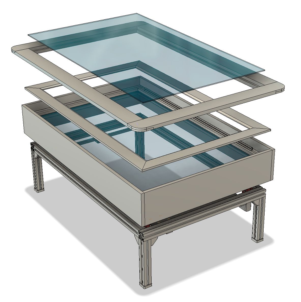
This is how the five layers stack from bottom to top: coreXY mechanism, glass bottom sandbox, LED strip cover, oak wood top cover frame, top cover glass. 


The biggest problem with the table now is that Ms. Kitty thinks it's hers, and throws everything I leave on it to the floor. I guess she likes it to be clear so she can chase the ball without crashing into anything.

Bearing replacements


 After I brought the table back home from the Maker Faire, it ran fine for a few hours then suddenly started making some terrible grinding noises when the Y axis moved. I surmised that the bearings were worn through and the mounting screws or metal pins were scraping on the aluminum t-slot.

I originally used PTFE for the sliding bearings in early iterations of The Spice Must Flow and Arrakis because I was pushing the stepper motors to their limits and wanted the lowest possible friction. The servomotors have much more "grunt" than the steppers did so I can afford a little more friction in trade for better wear resistance. I milled new bearings from some UHMW PE stock I found at the Makerspace and installed them in the Y axis bearing blocks and the magnet carriage. It runs quietly again, and hopefully the bearings will last longer than the PTFE did. 

Cat Proofing


Now that there's no "skirt" around the table, I needed to protect the belts and wiring from Ms. Kitty, who likes to chew on things she shouldn't. I cut a large piece of corrugated board from a TV box to fit the bottom of the table and used packing tape to hold it on the frame. Then I added a couple screws and t-nuts with a piece of fishing line to hold the hinged electronics panel up so it would be mostly out of sight.

underside of the table with the corrugated board in place.


View from the top side. If you look very closely you might see the fishing line that is holding the hinged electronics panel up.


CAD File


For those who are interested, you can download a Fusion360 STEP file here


Sunday, July 17, 2022

The CoreXY Belt "Tuning" Myth

I have seen uncountable forum posts, comments, emails, etc., about the need to "tune" belts in a corexy mechanism. The comments usually involve something about phone apps that read the frequency of a plucked belt and how you have to precisely match the tensions of the belts. The concept seems to scare off many would be corexy DIYers, thinking that there is some sort of voodoo required to get corexy machines to work properly. 

It's all nonsense.

There is one primary goal in setting the belt tension. It is to set the tension so that the X and Y axes are square. If they aren't square your prints won't be square- i.e. they will be distorted. What is more important to you, getting perfect middle C from the belts, or getting undistorted prints out of your machine?

It is apparently not obvious why tensioning the belts can affect the squareness of the axes so I have prepared some diagrams, below, that illustrate the concept. They are based on a diagram I have used a lot in the past so they may look familiar. I used UMMD's stacked belt layout, but the same concepts apply to any other belt layout you may use.

Fundamental assumption- you built the machine so that the X and Y axes are square when there are no belts on the mechanism. Don't assume you can use belt tension to correct for sloppy construction! If your axes aren't square without the belts, no ifs, ands, or buts, it's wrong. Fix it.


There are different ways to tension the belts, but adjustment must always be done on each belt, independently. If you move P3 or P4 in the Y direction, you tension both belts. That's not what we want to do. I illustrate tensioning by moving the motors. You could tension this belt by adjusting the attachments at the extruder carriage, or by having pulleys pressed against the belt between P3 and P4 or between the A motor and P4. 

Note: In the examples I use moving the motors to tension the belts because that's how I do it in my printer. It doesn't matter how you tension each belt- screw adjustments at the extruder carriage, moving motor, etc., the effect of the increased tension on the belt will be the same on the X axis.

When you move the A motor, P1 and P2 will experience forces created by the tension in the belt. There will be X and Y components of the forces at those pulleys, but we can ignore the X components because they don't affect the position of the X axis. The Y components of the force, illustrated by the green arrows are equal and in opposite directions. That is what causes the X axis to tilt out of square with the Y axis.

If everything is made of metal and bolted together tightly, how can the X axis possibly rotate out of square with the Y axis? Let's see... the Y axis bearing blocks to which the X axis rail is attached are not perfectly rigid and will deform slightly. The Y axis rails and whatever they are mounted on will also flex a little (especially if they are end-supported round rails). The X axis itself will also flex a little. All those little imperfections add up and will allow the X axis to tilt relative to the Y axis. Don't believe it? Try this experiment before you put belts on the mechanism:

Hold one end of the X axis against one of the mechanical stops at one end of the Y axis. Now grab the opposite end of the X axis and try to move it along the Y axis. Of course it moves. The X axis acts as a long lever arm against the opposite, fixed end of the axis. A little force applied at the free end turns into a big force at the opposite end of the axis, causing all those little flexures to occur. Notice that it doesn't take a lot of force to move the free end of the X axis. 

Also note, if you stood any of the pulleys up on their axles like fence posts, the mounts will flex, especially if they are anchored in printed plastic brackets. The printer's frame, if it's made out of thin materials such as plywood or 20mm square t-slot, will also distort, so you want to build your printer to minimize these problems- design pulley supports to hold the axles at the top and bottom, and build a rigid frame for the printer or at least its XY stage. The diagrams below ignore these problems.

Now imagine what adding the second belt is going to do:


2nd belt in place before it is tensioned...

Now tension the 2nd belt by moving the B motor.

Notice the forces created (red) are opposite those created when the first belt was tensioned (green). Also notice that the arrows representing all the forces are longer because tensioning the second belt (red) increases tension on the first belt (green).

The X axis rotates back into square with the Y axis and your printer will now be able to make undistorted prints.

 If your printer's mechanism were built with absolutely perfect mechanical symmetry, the belts would be equal in tension when the axes are square. No one builds printer mechanisms with perfect symmetry, therefore when the axes are square, the belts tensions will not be exactly equal. It doesn't matter. Belt driven linear positioning mechanisms work well over a wide range of belt tensions. 

I've put the above illustrations together into an animated .gif file:


Some manufacturers, such as Gates, have phone apps to set the belt tension based on the type and size of belt, the length of span, etc., so you can use it to set the tension to the manufacturer's specified optimal tension value (assuming you know what that value is, and can convert it to frequency). I wouldn't assume that all belts have the same optimal tension, so if you're using no-name Chinese belts and adjusting them to Gates specs, you may or may not be getting what you are expecting. OTOH, it's nice to have some objective indication of belt tension, even if it isn't optimal. The good news is that belt tension isn't critical al long as you set it high enough that the belts don't flop around but not so high that they cause excessive wear on the bearings in the motors or binding of the mechanism. "Tight, but not too tight" applies.

I hope this clears up some of the silliness that the internet always seems to provide a home for..